12
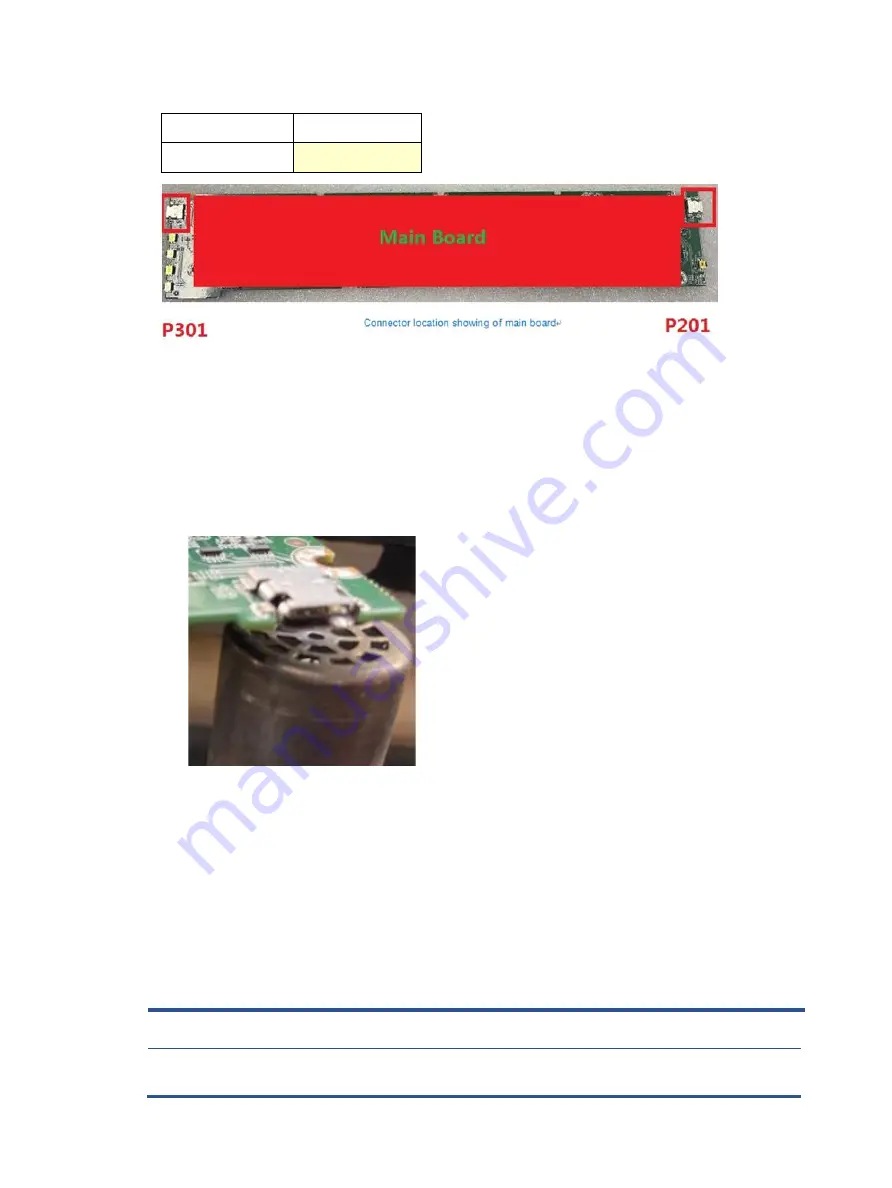
The connectors identifiers are as follows:
Connector
Location
USB-C
P201, P301
Before repairing connectors, follow these steps:
▲
Prepare the monitor for disassembly. See Preparation for disassembly on page 9.
USB-C connector P201, P301
Repair the USB-C connector:
1)
Use a hot air gun to heat the bottom side of PCB below the headphone connector.
Remove USB-C connector
USB-C connector repairing
2)
Lift the P201, P301 connector from the PCB.
3)
Place the new component on the PCB. Be sure that it matches the PCB footprint.
4)
Solder the new component
Function test
After repair, be sure to confirm that all functions are working.
Function test
After repair, be sure to confirm that all functions are working.
Table 4-1:
Function test
Te
st item
Operating description
Tool used
HDMI test
Confirm whether image displays and sound plays
correctly on the monitor.
Computer or DVD player
DP test
Confirm whether image displays and sound plays
correctly on the monitor.
Computer or DVD player
Audio test
Change volume and balance to confirm whether
Speaker
Table 4-1:
Function test
Test item
Operating description
Tool used
USB-C test
Confirm whether image displays and sound plays
correctly on the monitor.
Computer or DVD player


