background image

5.

If you want to change the size of the PIP, select 

PIP Size

 in the OSD then select either 

Large

 or

Small

.

6.

If you want to adjust the position of the PIP, select 

PIP Position

 in the OSD, then select either

Top Left

Top Right

Bottom Left

, or 

Bottom Right

.

DisplayPort Multistreaming

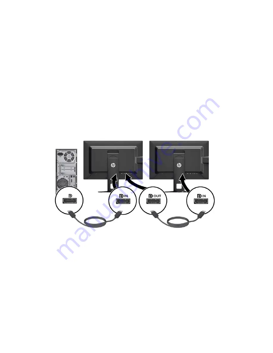
If you are using DisplayPort as the primary video input source, you can multistream to other
DisplayPort monitors connected in a daisy chain configuration. You can connect up to four monitors in
this configuration if supported by the graphics card.

To use DisplayPort multistreaming:

1.

Make sure that DisplayPort is used for your primary video input.

2.

Add a second monitor by connecting a DisplayPort cable between the DisplayPort OUT
connector on the primary monitor and the DisplayPort IN connector on a secondary multistream
monitor or the DisplayPort input connector on a secondary non-multistream monitor.

3.

You can set the connected monitor to display the same image as the primary monitor or a
different image. In the OSD for the connected monitor, select 

Management

 > 

DisplayPort

Output

 and select one of the following:

a.

DisplayPort 1.1 Compatibility Mode

 (default) - allows the same video image to be sent to

all monitors downstream of the monitor you are configuring

b.

DisplayPort 1.2

.- allows a different image to be sent to all monitors downstream of the

monitor you are configuring

4.

After setting the DisplayPort Compatibility Mode in the OSD, use the computer operating
system's display settings to set the display mode for the secondary monitor to either mirror the
image of the primary display or extend the second display for a different image from the primary
display.

If you wish to connect additional monitors downstream (up to four maximum), all but the final monitor
in the chain must support DisplayPort multstreaming.

28

Chapter 4   Operating the Monitor

Summary of Contents for DreamColor Z24X

Page 1: ...HP DreamColor Z24x Display User Guide ...

Page 2: ... services Nothing herein should be construed as constituting an additional warranty HP shall not be liable for technical or editorial errors or omissions contained herein This document contains proprietary information that is protected by copyright No part of this document may be photocopied reproduced or translated to another language without the prior written consent of Hewlett Packard Company F...

Page 3: ...xt set off in this manner indicates that failure to follow directions could result in bodily harm or loss of life CAUTION Text set off in this manner indicates that failure to follow directions could result in damage to equipment or loss of information NOTE Text set off in this manner provides important supplemental information iii ...

Page 4: ...iv About This Guide ...

Page 5: ...trols 13 Adjusting the Monitor 14 Turning on the Monitor 17 HP Watermark and Image Retention Policy 18 Connecting USB Devices 18 Removing the Monitor Stand 19 Mounting the Monitor 20 Mounting the Monitor Using the Quick Release 2 Mounting Bracket 20 Mounting the Monitor Without Using the Quick Release 2 Mounting Bracket 23 Locating the Serial Number and Product Number 24 Locating the Information C...

Page 6: ... 38 Z24x Model 38 Recognizing Preset Display Resolutions 39 Appendix B Support and Troubleshooting 40 Solving Common Problems 40 Product Support 41 Preparing to Call Technical Support 41 Appendix C Agency Regulatory Notices 43 Federal Communications Commission Notice 43 Modifications 43 Cables 43 Declaration of Conformity for Products Marked with the FCC Logo United States Only 43 Canadian Notice ...

Page 7: ...ousehold in the European Union 47 HP Recycling Program 47 Chemical Substances 47 Restriction of Hazardous Substances RoHS 47 Turkey EEE Regulation 48 Ukraine Restriction of Hazardous Substances 48 Appendix D LCD Monitor Quality and Pixel Policy 49 vii ...

Page 8: ...viii ...

Page 9: ...lor presets that allow you to re calibrate to a standard or custom color space by specifying the color primaries white point gamma and luminance requires the separately purchased HP DreamColor Calibration Solution kit Option to return to Factory Calibration settings or User Calibration settings to easily restore the monitor to the factory or user settings User calibration that requires the DreamCo...

Page 10: ...orted by your operating system Privacy filter slots to insert filters purchased separately to block side screen viewing Security slot provision on rear of monitor for optional cable lock Cable management feature for placement of cables and cords On Screen Display OSD adjustments in several languages for easy setup and screen optimization PIP functionality to enable the DisplayPort DVI and HDMI inp...

Page 11: ...e plug To reduce the risk of serious injury read the Safety and Comfort Guide It describes proper workstation setup posture and health and work habits for computer users and provides important electrical and mechanical safety information This guide is located on the Web at http www hp com ergo CAUTION For the protection of the monitor as well as the computer connect all power cords for the compute...

Page 12: ...re not covered under the HP warranty Slots and openings in the cabinet are provided for ventilation These openings must not be blocked or covered Never push objects of any kind into cabinet slots or other openings Do not drop the monitor or place it on an unstable surface Do not allow anything to rest on the power cord Do not walk on the cord Keep the monitor in a well ventilated area away from ex...

Page 13: ...vent damage to the monitor do not touch the surface of the LCD panel Pressure on the panel may cause non uniformity of color or disorientation of the liquid crystals If this occurs the screen will not recover to its normal condition If installing a base lay the monitor face down on a flat surface covered with a protective sheet foam or non abrasive cloth This prevents the screen from getting scrat...

Page 14: ...to the stand 1 Lay the monitor panel face down on a flat surface covered by a clean dry cloth 2 Slide the top of the mounting plate 1 on the stand under the upper lip of the recess in the back of the panel 3 Lower the bottom of the stand s mounting plate 2 into the recess until it snaps into place 4 The HP Quick Release 2 latch 3 pops up when the stand is locked in place NOTE If you are mounting t...

Page 15: ... the AC power cord to the monitor 4 DisplayPort IN Connects the DisplayPort cable to the monitor 5 DVI D Connects the DVI D cable to the monitor 6 HDMI Connects an HDMI cable to the monitor 7 DisplayPort OUT Connects a second monitor 8 Audio Out Connects headphones or optional HP Speaker Bar to the monitor 9 USB 3 0 Upstream Connector Connects the USB hub cable to the monitor s USB hub connector a...

Page 16: ...s 1 Place the monitor in a convenient well ventilated location near the computer 2 Before connecting the cables route the cables through the cable routing hole in the center of the stand 8 Chapter 3 Setting Up the Monitor ...

Page 17: ...the buttons and then press the bottom Open Menu button to open the OSD In the OSD select Video Input and choose the desired input source For DisplayPort digital operation connect the DisplayPort signal cable to the DisplayPort IN connector on the rear of the monitor and the other end to the DisplayPort connector on the computer cable provided NOTE You must connect the DisplayPort cable to the Disp...

Page 18: ...he monitor and the other end to the DVI connector on the computer cable provided For HDMI digital operation connect the HDMI signal cable to the HDMI connector on the rear of the monitor and the other end to the HDMI connector on the computer cable not provided 10 Chapter 3 Setting Up the Monitor ...

Page 19: ... connector on the rear panel of the computer and the other end to the upstream USB connector on the monitor NOTE The monitor supports USB 3 0 For optimal performance connect the USB cable to a USB 3 0 port on the computer if available Connecting the Cables 11 ...

Page 20: ...ble at all times Disconnect power from the computer by unplugging the power cord from the AC outlet If provided with a 3 pin attachment plug on the power cord plug the cord into a grounded earthed 3 pin outlet Do not disable the power cord grounding pin for example by attaching a 2 pin adapter The grounding pin is an important safety feature For your safety do not place anything on power cords or ...

Page 21: ...ht side of the screen and the button LEDs are lit 3 Power button Turns the monitor on or off NOTE Be sure the master power switch on the rear of the monitor is in the ON position to turn on the monitor NOTE To view an OSD menu simulator visit the HP Customer Self Repair Services Media Library at http www hp com go sml NOTE You can adjust the bezel button brightness and change the function of the b...

Page 22: ...sting the Monitor 1 Tilt the monitor s panel forward or backward to set it to a comfortable eye level 2 Swivel the monitor to the left or right for the best viewing angle 14 Chapter 3 Setting Up the Monitor ...

Page 23: ...ng to adapt to your application a Adjust the monitor to full height position and tilt the monitor back to full tilt position 1 b Pivot the monitor clockwise 90 from landscape to portrait orientation 2 CAUTION If the monitor is not in full height and full tilt position when pivoting the bottom right corner of the monitor panel will come in contact with the base and potentially cause damage to the m...

Page 24: ...ation sensor that automatically changes the displayed OSD from landscape to portrait when rotated Use the operating system s display settings to rotate the image on the screen from portrait to landscape 16 Chapter 3 Setting Up the Monitor ...

Page 25: ... be enabled To disable this feature press and hold the monitor power button for 10 seconds When the monitor is powered on a Monitor Status message is displayed for five seconds The message shows which input is the current active signal the status of the auto switch source setting On or Off factory default is On the default source signal factory default is DisplayPort the current preset display res...

Page 26: ...he screen for a prolonged period of time Static images may cause image retention damage that could look like stains or watermarks on the monitor s screen Monitors in use for 24 hours per day that result in image retention damage are not covered under the HP warranty To avoid image retention damage always turn off the monitor when it is not in use or use the power management setting if supported on...

Page 27: ...connected Also disconnect any other cables connected to the monitor 1 Disconnect and remove the signal power and USB cables from the monitor 2 Lay the monitor face down on a flat surface covered by a clean dry cloth 3 Press down on the latch near the bottom center of the monitor to unlock the HP Quick Release 2 1 4 Swing the bottom of the stand up until the mounting plate clears the recess in the ...

Page 28: ...party mounting solution to the monitor four 4 mm 0 7 pitch and 10 mm long screws are required Longer screws must not be used because they may damage the monitor It is important to verify that the manufacturer s mounting solution is compliant with the VESA standard and is rated to support the weight of the monitor display panel For best performance it is important to use the power and video cables ...

Page 29: ... Remove the four screws from the mounting plate to separate the mounting plate from its cover 3 Remove the four screws from the VESA holes located on the rear of the monitor panel Mounting the Monitor 21 ...

Page 30: ...nitor panel 5 Place the monitor panel on the mounting bracket you ve installed by aligning its recess with the mounting bracket then sliding it down over the top of the bracket and pressing it back into place against the bracket The release latch on the monitor will pop up when the monitor is safely locked in place 22 Chapter 3 Setting Up the Monitor ...

Page 31: ...e monitor panel directly to a mounting fixture without using the HP Quick Release 2 mounting bracket use the four screws removed from the VESA holes on the rear of the monitor panel and install them to attach the mounting device to the rear of the monitor panel Mounting the Monitor 23 ...

Page 32: ...ay head to read the label Locating the Information Card Identifying information is located on the pull out card and included on a label on the back of the monitor The card pulls out from behind the USB connectors on the left side of the panel Warranty support information model number serial number product number is printed on the front of the card and the label and regulatory information is printe...

Page 33: ...Installing a Cable Lock You can secure the monitor to a fixed object with an optional cable lock available from HP Installing a Cable Lock 25 ...

Page 34: ...crosoft Windows Plug and Play compatible and the monitor will work correctly without installing the INF file Monitor Plug and Play compatibility requires that the computer s graphic card is VESA DDC2 compliant and that the monitor connects directly to the graphics card Plug and Play does not work through separate BNC type connectors or through distribution buffers boxes The Image Color Matching Fi...

Page 35: ...d select the country region 2 Select the Drivers Downloads link then enter Z24x in the search box and click the Go button 3 Select your model then select your language and operating system 4 Download the software by following the instructions Using Picture in Picture PIP and Picture beside Picture PBP The monitor supports both PIP where one source is overlaid over another and PBP where one source ...

Page 36: ...DisplayPort input connector on a secondary non multistream monitor 3 You can set the connected monitor to display the same image as the primary monitor or a different image In the OSD for the connected monitor select Management DisplayPort Output and select one of the following a DisplayPort 1 1 Compatibility Mode default allows the same video image to be sent to all monitors downstream of the mon...

Page 37: ...matic fade out feature that is active by default The LEDs will fade after the OSD timeout period You can change the LED behavior so that they do not fade out and you can also adjust the brightness of the LEDs if the fade out feature is disabled To disable the bezel button fade out feature 1 Press one of the five front bezel buttons to activate the buttons and then press the bottom Open Menu button...

Page 38: ...he OSD press Management Auto Sleep Disable Using the On Screen Display Menu Use the On Screen Display OSD to adjust the screen image based on your viewing preferences To access the OSD do the following 1 Press any of the five buttons on the right side of the front bezel to activate the buttons 2 Press the bottom Open Menu button to open the OSD 3 Use the top four Function buttons to navigate selec...

Page 39: ...rrent Color Primaries u v xy Red x xxx x xxx Blue x xxx x xxx Green x xxx x xxx White Point u v xy x xxx x xxx Name of White Point ex D65 Gamma x x or sRGB Switch coordinate display to xy u v allows you to switch the information to display as either CIE 1931 xy or CIE 1976 u v Back Reset to Last Calibration Reset to Factory Calibration Back Using the On Screen Display Menu 31 ...

Page 40: ... Back Image Adjustment Aspect Ratio Display Fill to Source Aspect Ratio Proportional Fill to Entire Screen Non Proportional Pixel for Pixel Back Sharpness Soft Level 2 Level 3 Level 4 Sharp Back Dynamic Contrast Enable Disable Back Back Display Mode Information 32 Chapter 4 Operating the Monitor ...

Page 41: ... Large Small Back PIP Position Top Left Top Right Bottom Left Bottom Right Back PIP Input DisplayPort DVI HDMI Back Primary PIP Source Information Back Language Deutsch Traditional Chinese Simplified Chinese English Español Français Italiano Japanese Nederlands Português Using the On Screen Display Menu 33 ...

Page 42: ...ower On Recall Enable Disable Back DDC CI Communications Enable Disable Back Auto EDID Update Enable Disable Back Hot Plug Initiate Enable Disable Back DisplayPort Compatibility DisplayPort 1 1 Compatibility Mode DisplayPort 1 2 Back Back 34 Chapter 4 Operating the Monitor ...

Page 43: ... Configure Function Button 2 Configure Function Button 3 Configure Function Button 4 Bezel Button Brightness Set Brightness Value Back Bezel Button Auto Fade Enable Obey Menu Timeout Disable Always On Back Back Information Current Display Mode Display Mode Color Space Color Space Serial Number Serial Number Firmware Revision Firmware Revision IDs Last Calibration xxxxx Hours Backlight Hours xxxxx ...

Page 44: ...below the target luminance is possible for each color space while maintaining the accuracy of the primaries and the white point The RGB Adjust color selections are not calibrated and include Warm approximately 5000K Neutral approximately 6500K Cool approximately 9300 K Custom RGB user adjustable setting for red green and blue Color Calibration Factory Three standard color spaces sRGB AdobeRGB and ...

Page 45: ...r will be asked to input all the variables intended for use in the calibration process When calibration is complete the values are saved in monitor memory The most recent calibration settings can be re applied at any time through the On Screen Display Auto EDID Update By default the display automatically updates the display EDID when you switch color spaces If Auto EDID Update is enabled the EDID ...

Page 46: ...m 55 94 cm 20 67 inches 15 94 inches 9 37 inches 22 02 inches Maximum Graphic Resolution 1920 x 1200 60 Hz digital input Optimum Graphic Resolution 1920 x 1200 60 Hz digital input Environmental Requirements Temperature Operating Temperature Storage Temperature 5 to 35 C 20 to 60 C 41 to 95 F 4 to 140 F Power Source 100 240 VAC 50 60 Hz Input Terminal One DisplayPort IN connector one DVI connector ...

Page 47: ...576 16 9 50 i 27 000 9 720 576 16 9 50 p 27 000 10 800 600 4 3 60 317 40 000 11 1024 768 4 3 60 004 65 000 12 1280 720 16 9 24 p 59 400 13 1280 720 16 9 30 p 74 250 14 1280 720 16 9 50 p 74 250 15 1280 720 16 9 60 p 74 250 16 1280 1024 5 4 60 020 108 000 17 1366 768 16 9 60 000 72 000 18 1600 1200 4 3 60 000 162 000 19 1920 1080 16 9 24 p 74 250 20 1920 1080 16 9 30 p 74 250 21 1920 1080 16 9 50 i...

Page 48: ...y on the keyboard or move the mouse to inactivate the screen blanking utility Video card compatibility Open the OSD menu and select the Video Input menu Set Input Auto Switch Source to Disable and manually select the input Monitor will not turn on Master power switch on rear panel of the monitor is turned Off Turn the master power switch to On Image appears blurred indistinct or too dark Brightnes...

Page 49: ...ghtness and adjust the brightness value Displayed colors do not look correct Monitor is not calibrated Recalibrate monitor or perform a Factory Reset Calibration failed Incorrect setup or equipment failure Redo calibration Product Support For additional information on using your all in one go to http www hp com support Select your country or region select Troubleshooting and then enter your model ...

Page 50: ...e date on invoice Conditions under which the problem occurred Error messages received Hardware configuration Name and version of the hardware and software you are using 42 Appendix B Support and Troubleshooting ...

Page 51: ...iving antenna Increase the separation between the equipment and the receiver Connect the equipment into an outlet on a circuit different from that to which the receiver is connected Consult the dealer or an experienced radio or television technician for help Modifications The FCC requires the user to be notified that any changes or modifications made to this device that are not expressly approved ...

Page 52: ...ent sur le matériel brouilleur du Canada European Union Regulatory Notice Products bearing the CE marking comply with one or more of the following EU Directives as may be applicable Low Voltage Directive 2006 95 EC EMC Directive 2004 108 EC Ecodesign Directive 2009 125 EC R TTE Directive 1999 5 EC RoHS Directive 2011 65 EU Compliance with these directives is assessed using applicable European Harm...

Page 53: ...roved for use in that country The power cord must be rated for the product and for the voltage and current marked on the product s electrical ratings label The voltage and current rating of the cord should be greater than the voltage and current rating marked on the product In addition the cross sectional area of the wire must be a minimum of 0 75 mm or 18 AWG and the length of the cord must be be...

Page 54: ... provided with ENERGY STAR qualified computers and displays The default power management settings on ENERGY STAR qualified computers are preset to behave in the following ways when the system is operating on AC power Turn off an external display after 15 minutes of user inactivity Initiate a low power sleep mode for the computer after 30 minutes of user inactivity ENERGY STAR qualified computers e...

Page 55: ...p where you purchased the product HP Recycling Program HP encourages customers to recycle used electronic hardware HP original print cartridges and rechargeable batteries For more information about recycling programs go to http www hp com recycle Chemical Substances HP is committed to providing our customers with information about the chemical substances in our products as needed to comply with le...

Page 56: ...of Hazardous Substances The equipment complies with requirements of the Technical Regulation approved by the Resolution of Cabinet of Ministry of Ukraine as of December 3 2008 No 1057 in terms of restrictions for the use of certain dangerous substances in electrical and electronic equipment 48 Appendix C Agency Regulatory Notices ...

Page 57: ...ub pixel A defective whole pixel is always turned on a bright spot on a dark background or it is always off a dark spot on a bright background The first is the more visible of the two A defective sub pixel dot defect is less visible than a defective whole pixel and is small and only visible on a specific background To locate defective pixels the monitor should be viewed under normal operating cond...

Reviews: