background image

Removal and Replacement Procedures 

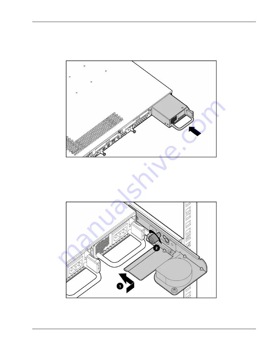
To install a hot-plug power supply: 

1.  Remove the protective cover from the connector on the power supply. 

2.  Slide the power supply into the chassis until it snaps into place. 


Figure 2-21:  Installing a power supply (cables removed for clarity) 

3.  If you are replacing the power supply from hot-plug power supply bay 1, and there is a 

sliding rail solution in place: 

a.  Push the cable retractor toward the rack rail and toward the chassis (1). 

b.  Tighten the cable retractor thumbscrew (2). 


Figure 2-22:  Returning the cable retractor (cables removed for 
clarity) 

HP ProLiant DL360 Generation 3 Server Maintenance and Service Guide 

2-21 


Summary of Contents for DL360 - ProLiant - Photon

Page 1: ...HP ProLiant DL360 Generation 3 Server Maintenance and Service Guide March 2004 Fifth Edition Part Number 293948 005 ...

Page 2: ...contained herein The information in this document is provided as is without warranty of any kind and is subject to change without notice The warranties for HP products are set forth in the express limited warranty statements accompanying such products Nothing herein should be construed as constituting an additional warranty HP ProLiant DL360 Generation 3 Server Maintenance and Service Guide March ...

Page 3: ...rnings and Precautions 2 3 Preparation Procedures 2 4 Hot Plug Devices 2 4 Non Hot Plug Devices 2 4 Powering Down the Server 2 4 Removing the Server from the Rack 2 6 Server Access Panel 2 7 Processor Fan Module 2 8 Mass Storage Devices 2 10 Drive Locations 2 10 Hard Drive Blank 2 11 Hot Plug U320 SCSI Hard Drives 2 11 Optical Device 2 13 Optical Device Ejector 2 15 Diskette Drive 2 18 Hot Plug Po...

Page 4: ... Components for Remote ROM Flash 4 4 SmartStart Software 4 4 SmartStart Autorun Menu 4 5 SmartStart Scripting Toolkit 4 5 Enterprise Diagnostics LX32 Utility 4 5 Chapter 5 LEDs Switches and Jumpers Status Indicators 5 1 Front Panel LED Indicators 5 1 Rear Panel LED Indicators 5 3 System Board LEDs 5 4 Switches 5 5 System Maintenance Switch SW2 5 6 Hot Plug Redundant Power Supply PCI Switch SW1 Set...

Page 5: ...ir Because of the complexity of the individual boards and subassemblies no one should attempt to make repairs at the component level or to make modifications to any printed wiring board Improper repairs can create a safety hazard WARNING To reduce the risk of personal injury from electric shock and hazardous energy levels do not exceed the level of repairs specified in these procedures Because of ...

Page 6: ...server CAUTION The computer is designed to be electrically grounded earthed To ensure proper operation plug the AC power cord into a properly grounded AC outlet only NOTE Any indications of component replacement or printed wiring board modifications may void any warranty vi HP ProLiant DL360 Generation 3 Server Maintenance and Service Guide ...

Page 7: ...cludes an integrated nonvolatile management log that contains fault and management information The contents of the Integrated Management Log IML can be viewed with Insight Manager Telephone Numbers For the name of the nearest HP authorized reseller In the United States call 1 800 345 1518 In Canada call 1 800 263 5868 For HP technical support In the United States and Canada call 1 800 652 6672 Out...

Page 8: ... parts list for the HP ProLiant DL360 Generation 3 server Refer to Table 1 1 for the names and part numbers of the referenced spare parts Mechanical Components Exploded View Figure 1 1 Mechanical components exploded view HP ProLiant DL360 Generation 3 Server Maintenance and Service Guide 1 1 ...

Page 9: ... Number 1 Access panel 307526 001 2 Plastics kit a Power supply fan baffle b Left bezel 305451 001 3 Hardware kit a Power supply blank b PCI blank 305452 001 System Components Exploded View Figure 1 2 System components exploded view 1 2 HP ProLiant DL360 Generation 3 Server Maintenance and Service Guide ...

Page 10: ... K cache processor 305437 001 c 3 06 GHz 533 MHz 512 K cache processor 325148 001 d 2 80 GHz 533 MHz 1 MB cache processor 360224 001 e 3 06 GHz 533 MHz 1 MB cache processor 341764 001 f 3 20 GHz 533 MHz 1 MB cache processor 349335 001 g 3 20 GHz 533 MHz 2 MB cache processor 360223 001 11 Battery backed write cache battery module 260740 001 12 Optical device diskette drive interface board 305450 00...

Page 11: ...01 e 72 GB 15 K hard drive 289243 001 f 146 GB 10K hard drive 289044 001 20 System fan assembly 307525 001 21 Power converter module 305446 001 22 325 W power supply 305447 001 23 400 W DC power supply 338887 001 24 System board battery 234556 001 25 Country kit 309480 001 26 Return kit 173842 001 27 Fixed rail kit 310619 001 28 Sliding rail kit 310618 001 29 Telco rack mounting kit 252367 001 30 ...

Page 12: ...sitive devices or micro circuitry Proper packaging and grounding techniques are necessary to prevent damage To prevent electrostatic damage observe the following precautions Transport products in static safe containers such as conductive tubes bags or boxes Keep electrostatic sensitive parts in their containers until they arrive at static free stations Cover workstations with approved static dissi...

Page 13: ...before touching This symbol indicates the presence of hazardous energy circuits or electric shock hazards Refer all servicing to qualified personnel WARNING To reduce the risk of injury from electric shock hazards do not open this enclosure Refer all maintenance upgrades and servicing to qualified personnel This symbol on an RJ 45 receptacle indicates a network interface connection WARNING To redu...

Page 14: ... over 2 1m 7 ft tall and may become unstable when being moved on its casters Do not stand in front of the rack as it rolls down the ramp from the pallet but handle the rack from both sides Server Warnings and Precautions WARNING To reduce the risk of personal injury from hot surfaces allow the hot plug drives and the internal system components to cool before touching WARNING To reduce the risk of ...

Page 15: ... server WARNING To reduce the risk of injury from electric shock remove the power cord to completely disconnect power from the system WARNING To reduce the risk of personal injury or damage to the equipment ensure that only one component is extended at a time A rack may become unstable if more than one component is extended for any reason WARNING Because the rack allows you to stack computer compo...

Page 16: ...n earlier in this chapter To power down the server 1 Shut down the operating system as directed in the operating system instructions CAUTION Whenever installing hardware or performing maintenance procedures requiring access to internal components it is recommended that all server data be backed up to avoid loss 2 Press the Unit Identification switch on the server front panel 1 An LED illuminates b...

Page 17: ...isconnect all remaining cables from the server rear panel including cables extending from expansion boards b Loosen the thumbscrews securing the server to the rack c Slide the server out of the rack until the rail locks engage d Press and hold the rail locks extend the server until it clears the rack 2 If the server has a universal rail solution a Disconnect all remaining cables from the server re...

Page 18: ... 3 Removing the server from the rack Reverse these procedures to replace the server into the rack Server Access Panel WARNING To reduce the risk of personal injury from hot surfaces allow the internal system components to cool before touching them CAUTION Before removing the server access panel be sure that the server is powered down and that the power cord is disconnected from the server or the e...

Page 19: ...verse steps 1 and 2 to replace the access panel Processor Fan Module To remove the processor fan module 1 Power down the server Refer to Powering Down the Server earlier in this chapter 2 Remove the server from the rack Refer to Removing the Server from the Rack earlier in this chapter 3 Remove the access panel Refer to Server Access Panel earlier in this chapter 2 8 HP ProLiant DL360 Generation 3...

Page 20: ...le from the rear 2 to release it from the system board Figure 2 5 Loosening the processor fan module thumbscrew 6 Remove the processor fan module from the chassis Figure 2 6 Removing the processor fan module Reverse steps 1 through 6 to install the processor fan module HP ProLiant DL360 Generation 3 Server Maintenance and Service Guide 2 9 ...

Page 21: ...ve This section describes the drive cage positions and removal and replacement procedures for these mass storage devices Drive Locations Figure 2 7 Server drive locations Table 2 1 Server Drive Locations Location Description 1 Low profile 3 5 inch 1 44 MB diskette drive 2 Low profile optical device 3 Hot plug U320 SCSI hard drive SCSI ID 0 4 Hot plug U320 SCSI hard drive SCSI ID 1 2 10 HP ProLiant...

Page 22: ...ce Hot Plug U320 SCSI Hard Drives To assess a hard drive s status you must observe and understand the hot plug hard drive status LEDs For a detailed explanation of hard drive status LEDs refer to the HP ProLiant DL360 Generation 3 Server Setup and Installation Guide WARNING Read Hot plug Hard Dr ive Replacement Guidelines in the HP ProLiant Servers Troubleshooting Guide before removing a hard driv...

Page 23: ...tch on the hard drive 2 3 Pull the hard drive to remove it from the server 3 Figure 2 9 Removing a hot plug U320 SCSI hard drive IMPORTANT The ProLiant DL360 Generation 3 server supports HP Universal U320 drives only Compaq branded Ultra3 or HP branded U160 hot plug drives are not supported 2 12 HP ProLiant DL360 Generation 3 Server Maintenance and Service Guide ...

Page 24: ...ug U320 SCSI hard drive Optical Device The server supports a diskette drive and an optical device The optical device and the diskette drive may be removed independently CAUTION Do not operate the server without an optical device installed Failure to install an optical device can lead to improper cooling and may damage the system HP ProLiant DL360 Generation 3 Server Maintenance and Service Guide 2...

Page 25: ... ejector button to release the optical device 1 NOTE Access to the optical device ejector button is intentionally restricted Push the optical device ejector button with a small flat object such as a key or pen to eject the optical drive 3 Grasp the optical device and remove it from the optical device bay 2 Figure 2 11 Removing the optical device 2 14 HP ProLiant DL360 Generation 3 Server Maintenan...

Page 26: ...ce Ejector To remove the optical device ejector 1 Power down the server Refer to Powering Down the Server earlier in this chapter 2 Remove the optical device Refer to Optical Device earlier in this chapter 3 Remove all hard drive blanks and hot plug U320 SCSI hard drives Refer to Hard Drive Blank and Hot Plug U320 SCSI Hard Drives earlier in this chapter 4 Partially extend the server to gain acces...

Page 27: ...o release it from the chassis NOTE Access to the tab on the side of the optical device ejector is restricted To push in the tab on the optical device ejector use a small flat object such as a key screwdriver or pen 7 Lower the optical device ejector and remove it from the chassis 2 Figure 2 14 Removing the optical device ejector from the chassis 2 16 HP ProLiant DL360 Generation 3 Server Maintenan...

Page 28: ...into the slot in the chassis 2 until the tab clicks in to place Figure 2 15 Inserting the optical device ejector into the chassis 10 Replace the screws securing the optical device ejector to the chassis Figure 2 16 Replacing the optical device ejector screws HP ProLiant DL360 Generation 3 Server Maintenance and Service Guide 2 17 ...

Page 29: ...emoving the Server from the Rack earlier in this chapter 3 Remove the access panel Refer to Server Access Panel earlier in this chapter 4 Remove the hot plug U320 SCSI hard drive located below the diskette drive Refer to Hot Plug U320 SCSI Hard Drives earlier in this chapter 5 Remove the diskette drive retaining screw 1 6 Push the diskette drive from the rear to release it from the backplane conne...

Page 30: ... access panel Refer to Server Access Panel earlier in this chapter 5 Replace the server in the rack Refer to Removing the Server from the Rack earlier in this chapter 6 Connect the power cord s 7 Press the Power On Standby switch to power on the server and resume normal operations Hot Plug Power Supplies The procedures in this section assume that the server is configured with two power supplies To...

Page 31: ...m the server chassis and then away from the rack rail 2 Figure 2 19 Moving the cable retractor to access the power supply in hot plug power supply bay 1 cables removed for clarity 3 Grasp the handle on the power supply 4 Push the power supply ejector button 1 5 Pull the power supply from the server 2 Figure 2 20 Removing a power supply cables removed for clarity 2 20 HP ProLiant DL360 Generation 3...

Page 32: ...alling a power supply cables removed for clarity 3 If you are replacing the power supply from hot plug power supply bay 1 and there is a sliding rail solution in place a Push the cable retractor toward the rack rail and toward the chassis 1 b Tighten the cable retractor thumbscrew 2 Figure 2 22 Returning the cable retractor cables removed for clarity HP ProLiant DL360 Generation 3 Server Maintenan...

Page 33: ...his chapter 4 Loosen the PCI riser board thumbscrew 1 5 Lift the front of the assembly slightly 2 and then pull it out from the server chassis PCI expansion board slot 3 Figure 2 23 Removing the PCI riser board assembly Reverse steps 1 through 5 to replace the PCI riser board assembly Replacing an Expansion Board To replace an expansion board 1 Power down the server Refer to Powering Down the Serv...

Page 34: ...CI riser board assembly 6 Align the expansion board with the guiding groove 7 Slide the expansion board into the slot until the board firmly seats Figure 2 25 Installing an expansion board into the PCI riser board assembly 8 Install the PCI riser board assembly into the appropriate PCI expansion board slot Refer to PCI Riser Board Assembly earlier in this chapter HP ProLiant DL360 Generation 3 Ser...

Page 35: ...r board assembly Refer to PCI Riser Board Assembly earlier in this chapter 5 Disconnect the fan power cables from the optical device diskette drive interface board 1 6 Disconnect the optical device diskette drive interface board power cable from the optical device diskette drive interface board 2 7 Remove the optical device diskette drive interface board power cable from the clip on the side of th...

Page 36: ...gh 8 to replace the fan assembly Power Converter Module To remove the power converter module 1 Power down the server Refer to Powering Down the Server earlier in this chapter 2 Remove the server from the rack Refer to Removing the Server from the Rack earlier in this chapter 3 Remove the access panel Refer to Server Access Panel earlier in this chapter HP ProLiant DL360 Generation 3 Server Mainten...

Page 37: ...the back of the chassis and remove it 2 Figure 2 28 Removing the power supply fan baffle 5 If the server is configured with a PCI riser board assembly in PCI expansion board slot 2 a Remove the hot plug power supply Refer to Hot Plug Power Supplies earlier in this chapter b Remove the PCI riser board assembly from PCI expansion board slot 2 Refer to PCI Riser Board Assembly earlier in this chapter...

Page 38: ...of the I O fan assembly 2 Figure 2 29 Disconnecting the optical device diskette drive interface board power cable 8 Loosen the thumbscrew securing the power converter module to the chassis 1 9 Slide the power converter module toward the rear of the chassis and remove it 2 Figure 2 30 Removing the power converter module from the chassis HP ProLiant DL360 Generation 3 Server Maintenance and Service ...

Page 39: ...ice Diskette Drive Interface Board To remove the optical device diskette drive interface board 1 Power down the server Refer to Powering Down the Server earlier in this chapter 2 Remove the server from the rack Refer to Removing the Server from the Rack earlier in this chapter 3 Remove the access panel Refer to Server Access Panel earlier in this chapter 4 Remove the optical device and diskette dr...

Page 40: ...isconnect the optical device diskette drive cable 1 7 Loosen the thumbscrews securing the interface board to the server chassis 2 8 Pull the interface board forward tip it and remove it from the server chassis 3 Figure 2 33 Removing the optical device diskette drive interface board from the chassis Reverse steps 1 through 8 to replace the optical device diskette interface board HP ProLiant DL360 G...

Page 41: ...in this chapter 3 Remove the access panel Refer to Server Access Panel earlier in this chapter 4 Remove the optical device diskette drive interface board Refer to Optical Device Diskette Drive Interface Board earlier in this chapter 5 Lift the SCSI backplane board until it clears the server Figure 2 34 Removing the SCSI backplane Reverse steps 1 through 5 to replace the SCSI backplane 2 30 HP ProL...

Page 42: ...B 512 MB 1 GB or 2 GB DDR SDRAM DIMMs DIMMs must be installed in pairs and be of the same size Install DIMMs only in one direction Be sure to match the notch on the module with the tab on the DIMM slot Before seating the DIMM in the slot ensure that the module key is fully inserted Use only HP DDR SDRAM DIMMs DIMMs from other sources may affect data integrity Install DDR SDRAM DIMM modules one at ...

Page 43: ...ted and properly seated IMPORTANT DIMMs must be installed in pairs and must be of the same size IMPORTANT DIMMs must be 266 MHz PC2100 DDR SDRAM 3 3 volts 72 bits wide and ECC To remove a DIMM 1 Power down the server Refer to Powering Down the Server earlier in this chapter 2 Remove the server from the rack Refer to Removing the Server from the Rack earlier in this chapter 3 Remove the access pane...

Page 44: ...M with the tab in the expansion socket 2 Insert the DIMM at the same angle as the DIMM socket on the system board 1 3 Press the DIMM firmly until the latches close 2 Figure 2 37 Installing a DDR SDRAM DIMM into the expansion socket HP ProLiant DL360 Generation 3 Server Maintenance and Service Guide 2 33 ...

Page 45: ...ket 1 must always be populated 3 Processor socket 2 4 PPM socket 2 Note A PPM must be installed when a new processor is installed WARNING To reduce the risk of personal injury from hot surfaces allow the internal system components to cool before touching CAUTION Processor socket 1 must be populated at all times Failure to follow this process results in the system failing to boot and halting during...

Page 46: ...e the server from the rack Refer to Removing the Server from the Rack earlier in this chapter 3 Remove the access panel Refer to Server Access Panel earlier in this chapter 4 Unlatch processor heatsink retaining clips 1 5 Remove the heatsink 2 Figure 2 39 Removing a heatsink HP ProLiant DL360 Generation 3 Server Maintenance and Service Guide 2 35 ...

Page 47: ...k when replacing processors Failure to use new components may result in damage to the processor CAUTION Make sure the processor locking lever is open before inserting the processor into the processor socket Attempting to insert the processor with the processor locking lever closed may result in damage to the processor 2 36 HP ProLiant DL360 Generation 3 Server Maintenance and Service Guide ...

Page 48: ...the socket CAUTION Heatsinks have an integrated plastic covered thermal pad Remove the plastic cover from the new heatsink to expose the adhesive side of the thermal pad before placing the heatsink on the processor 3 Remove the protective covering from the heatsink Figure 2 42 Removing the heatsink protective covering HP ProLiant DL360 Generation 3 Server Maintenance and Service Guide 2 37 ...

Page 49: ...clips 2 Figure 2 43 Installing the heatsink onto the processor and closing the locking latches Processor Power Module Each processor has an associated PPM Figure 2 38 shows the location of the processors and PPMs on the system board To replace a PPM 1 Power down the server Refer to Powering Down the Server earlier in this chapter 2 Remove the server from the rack Refer to Removing the Server from ...

Page 50: ...Removing a processor power module 6 Install a new PPM into the socket 1 7 Close the locking latches 2 Figure 2 45 Installing a processor power module NOTE PPMs with the same part number may look different but they are functionally equivalent HP ProLiant DL360 Generation 3 Server Maintenance and Service Guide 2 39 ...

Page 51: ...to Server Access Panel earlier in this chapter 4 Remove the PCI riser board assembly from slot 1 Refer to PCI Riser Board Assembly earlier in this chapter 5 Remove the battery module cable from the battery backed write cache BBWC cable clip 1 6 Disconnect the BBWC cable from the SmartArray 5i Plus Controller connector 2 and the BBWC battery module 3 Figure 2 46 Disconnecting the battery backed wri...

Page 52: ...date and time you may need to replace the battery that provides power to the real time clock With normal use battery life is usually about 5 to 10 years Replace used batteries with HP 540 milliampere hour lithium 3 V replacement batteries P N 179322 001 WARNING To reduce the risk of electric shock or equipment damage Do not disable the power cord grounding plug The grounding plug is an important s...

Page 53: ...hapter 3 Remove the access panel Refer to Server Access Panel earlier in this chapter 4 Remove the battery backed write cache enabler battery pack Refer to Battery Backed Write Cache Enabler earlier in this chapter 5 Locate the battery holder on the system board Figure 2 48 Battery location 6 Remove the existing battery Figure 2 49 Removing the system battery 2 42 HP ProLiant DL360 Generation 3 Se...

Page 54: ...cess Panel earlier in this chapter 4 Remove the processor fan module Refer to Processor Fan Module earlier in this chapter 5 Remove the SCSI backplane board Refer to SCSI Backplane Board earlier in this chapter 6 Remove the I O system fan assembly Refer to I O System Fan Assembly earlier in this chapter 7 Remove the power converter module Refer to Power Converter Module earlier in this chapter 8 L...

Page 55: ...startup sequence press the F9 key to access RBSU 2 Select the System Options menu 3 Select Serial Number The following warning is displayed WARNING WARNING WARNING The serial number is loaded into the system during the manufacturing process and should NOT be modified This option should ONLY be used by qualified service personnel This value should always match the serial number sticker located on t...

Page 56: ...e that the cables are not in a position where they will be pinched or crimped Figure 3 1 identifies the proper routing of the cables for the HP ProLiant DL360 Generation 3 server Figure 3 1 Routing of server cables HP ProLiant DL360 Generation 3 Server Maintenance and Service Guide 3 1 ...

Page 57: ...ioning properly the system periodically resets the timer However when the operating system fails the timer expires and restarts the server ASR 2 increases server availability by restarting the server within a specified time after a system hang or shutdown At the same time the Insight Manager 7 console notifies the user by sending a message to a designated pager number that ASR 2 has restarted the ...

Page 58: ...es server health and remote server manageability The iLO subsystem includes an intelligent microprocessor secure memory and a dedicated network interface This design makes iLO technology independent of the host server and its operating system The iLO subsystem provides remote access to any authorized network client sends alerts and provides other server management functions Using iLO technology it...

Page 59: ...ftware is the preferred method for rapid high volume server deployments The Rapid Deployment Pack software integrates two powerful products Altiris eXpress Deployment Server and the ProLiant Integration Module The intuitive graphical user interface of the Altiris eXpress Deployment Server console provides simplified point and click and drag and drop solutions that enable the deployment of target s...

Page 60: ...OM images across a wide range of servers and array controllers This tool has the following features Works offline and online Supports Microsoft Windows NT Windows 2000 Novell NetWare and Linux operating systems Integrates with other software maintenance deployment and operating system tools Automatically checks for hardware firmware and operating system dependencies and installs only the correct R...

Page 61: ... directly from the operating system environment simply by inserting the SmartStart CD into a configured system The Autorun Menu can Install the latest ProLiant Support Packs Download specific drivers and utilities SmartStart Scripting Toolkit The SmartStart Scripting Toolkit is a set of Microsoft MS DOS based utilities that configure and deploy servers in a customized predictable and unattended ma...

Page 62: ... LED indicators System board LEDs Use the following sections to determine the location and status of LEDs on the server Front Panel LED Indicators The set of six LEDs on the front of the server indicates server status The following figure and table identify and describe the location and function of the LEDs Figure 5 1 Identifying the front panel LED indicators HP ProLiant DL360 Generation 3 Server...

Page 63: ...al health LED power supply Amber Power redundancy failure Green Normal 4 NIC 1 link activity LED Green Network link Blinking Network link and activity Off No link to the network If power is off view the rear panel RJ 45 LEDs 5 NIC 2 link activity LED Green Network link Blinking Network link and activity Off No link to the network If the power is off view the rear panel RJ 45 LEDs 6 Power On Standb...

Page 64: ...s Table 5 2 Rear Panel LED Indicators Item LED Status 1 iLO link On Link Off No Link 2 iLO activity Off No Activity Blinking Activity 3 10 100 1000 NIC 1 Green Network link Blinking Network link and activity Off No link to the network 4 10 100 1000 NIC 2 Green Network link Blinking Network link and activity Off No link to the network 5 Rear Unit Identification LED switch Blue Activated Blinking Sy...

Page 65: ...5 3 System Board LEDs and Switches Item Description 1 Interlock LED 2 System debug LEDs 8 total 3 DIMM error LEDs 4 total 4 PPM 1 error LED 5 CPU 1 error LED 6 CPU 2 error LED 7 Overtemperature error LED 8 CPU fan failure LED 9 PPM 2 error LED 10 I O fan failure LED 11 Debug LED switch SW3 12 Hot plug redundant power supply PCI install switch SW1 13 System maintenance switch SW2 5 4 HP ProLiant DL...

Page 66: ...the server may not work properly and you may receive error messages on the screen IMPORTANT Reserved switches are provided for use by HP authorized service providers only and should not be changed from the indicated default settings Refer to Figure 5 3 and Table 5 3 for locations on the system board of the switches The following subsections provide reference information about setting the system bo...

Page 67: ...d setting On Override RBSU setting and override password prompts S6 Reset configuration Off Off No function On ROM reads system configuration as invalid reset configuration S7 Reserved Off Reserved S8 Reserved Off Reserved Note On activates the function Hot Plug Redundant Power Supply PCI Switch SW1 Settings The hot plug redundant power supply PCI switch SW1 is a four position switch used for syst...

Page 68: ...assword IMPORTANT This method of clearing and resetting system passwords is necessary only if the current password is not known Otherwise when prompted the password can be entered followed by a forward slash This operation removes the current password and allows one of the following to be performed Enter the RBSU and set the password to a new value Leave the password value blank to disable the pas...

Page 69: ...tup and Installation Guide for complete instructions on configuring the server To clear and reset the system configuration settings follow the procedures outlined in the Clearing and Resetting System Password Settings section earlier in this chapter replacing switch position S6 for S5 After completing the steps press the F9 key to run the RBSU and reset all system configuration settings NOTE For c...

Page 70: ... 42 62 cm 16 78 in Weight maximum 16 78 kg 37 lb Weight no drives installed 12 47 kg 27 5 lb Input requirements Rated input voltage 100 VAC to 240 VAC Rated input frequency 50 Hz to 60 Hz Rated input current 3 8 A 110 V to 1 9 A 220 V Rated input power 425 W BTUs per hour 1458 Power supply output Rated steady state power 325 W Maximum peak power 325 W continued HP ProLiant DL360 Generation 3 Serve...

Page 71: ... to 35 C 50 F to 95 F Shipping Refer to note 40 C to 60 C 40 F to 140 F Relative humidity noncondensing 1 Operating 10 to 90 Non operating 5 to 95 Maximum wet bulb temperature 28 C 82 4 F 1 Operating temperature has an altitude derating of 1 C per 304 8 M 1 8 F per 1 000 ft No direct sunlight Storage maximum humidity of 95 is based on a maximum temperature of 45 C 113 F Altitude minimum for storag...

Page 72: ... in a PCI riser board assembly BIOS upgrade 4 4 removing 2 22 blanks replacing 2 23 hard drive 2 11 PCI 1 2 F power supply 1 2 fan assembly removing 2 24 C replacing 2 25 cable retractor flash ROM 4 4 removing 2 20 floppy disk drive See diskette drive replacing 2 21 frequency rated input 6 1 cable routing diagram 3 1 front panel LEDs See LEDs CMOS clearing 5 8 component level repairs v G configura...

Page 73: ...ntegrated Lights Out iLO 4 2 ORCA See Option ROM Configuration for Arrays Integrated Management Log IML 4 2 P K part numbers 1 2 1 3 kits parts catalog illustrated 1 1 country 1 4 password protection fixed rail 1 4 clear and reset 5 7 hardware 1 2 how to set up 5 7 plastics 1 2 PCI blank 1 2 Telco rack mounting 1 4 PCI riser board assembly removing 2 22 L replacing 2 22 LEDs plastics kit 1 2 front...

Page 74: ...ated steady state power 6 1 optical device diskette drive interface board 2 28 relative humidity nonoperating 6 2 relative humidity operating 6 2 PCI riser board assembly 2 22 removing from the rack 2 6 power converter module 2 25 replacing into the rack 2 7 power supply 2 19 shipping temperature range 6 2 processor 2 35 size 6 1 processor fan module 2 8 temperature range 6 2 processor power modul...

Page 75: ...em components exploded view illustrated 1 2 ventilation clearances vi T voltage rated input 6 1 technical support W Canada vii other countries vii warranty vi United States vii weight server 6 1 technician notes v wet bulb temperature server 6 2 telephone numbers vii temperature server 6 2 Index 4 HP ProLiant DL360 Generation 3 Server Maintenance and Service Guide ...

Reviews: