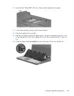
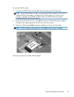
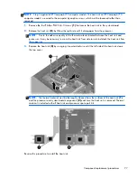
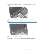
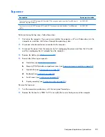
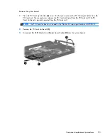
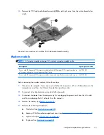
7.
If it is necessary to replace the display hinges, remove the following:
(1)
Four rubber screw covers from the display bezel top edge
(2)
Four Torx T8M2.5×6.0 screws from the display bezel top edge
(3)
Two rubber screw covers from the display bezel bottom edge
(4)
Two Torx T8M2.5×7.0 screws from the display bezel top edge
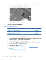
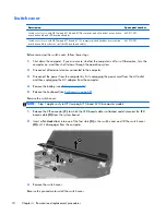
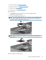
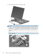
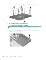
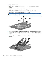
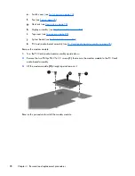
8.
Flex the inside edges of the left and right sides
(1)
and the top and bottom sides
(2)
of the display
bezel until the bezel disengages from the display enclosure.
9.
Remove the display bezel
(3)
.
NOTE:
The display bezel is available using spare part number 446871-001.
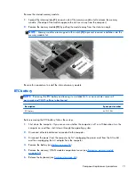
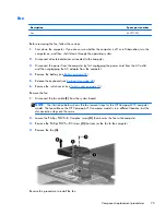
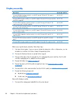
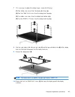
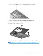
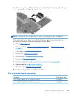
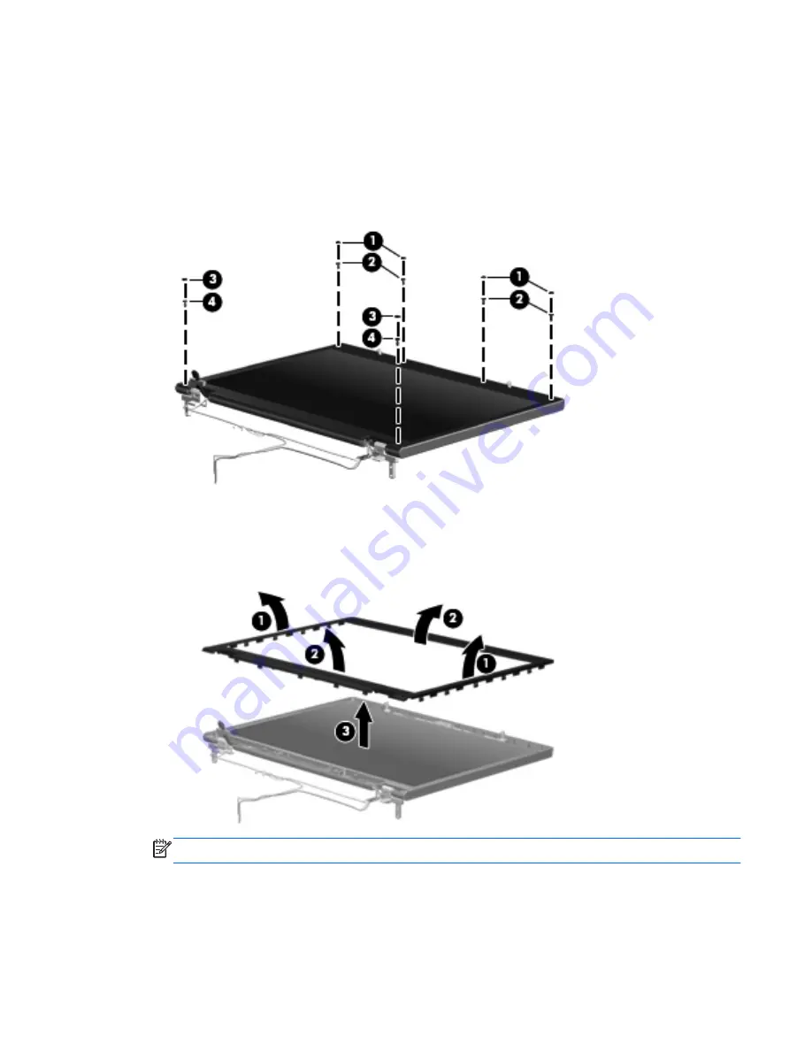
10.
Remove the four Torx T8M2.5×6.0 screws
(1)
that secure the display panel to the display
enclosure.
Component replacement procedures
83
Summary of Contents for Compaq 6710b
Page 4: ...iv Safety warning notice ...
Page 9: ...Index 164 ix ...
Page 10: ...x ...
Page 34: ...Computer major components 24 Chapter 3 Illustrated parts catalog ...
Page 124: ...Startup time 15 seconds Stop time 6 seconds 114 Chapter 6 Specifications ...
Page 178: ......


