e.
Switch cover (see
Switch cover on page 74
)
f.
Fan (see
Fan on page 75
)
g.
Heat sink (see
Heat sink on page 76
)
h.
Display assembly (see
Display assembly on page 80
)
i.
Top cover (see
Top cover on page 85
)
j.
System board (see
System board on page 92
)
k.
PC Card/audio board assembly (see
PC Card/audio board assembly on page 95
)
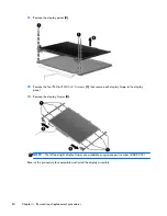
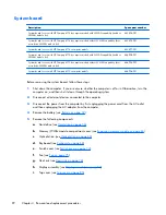
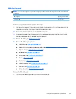
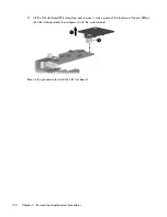
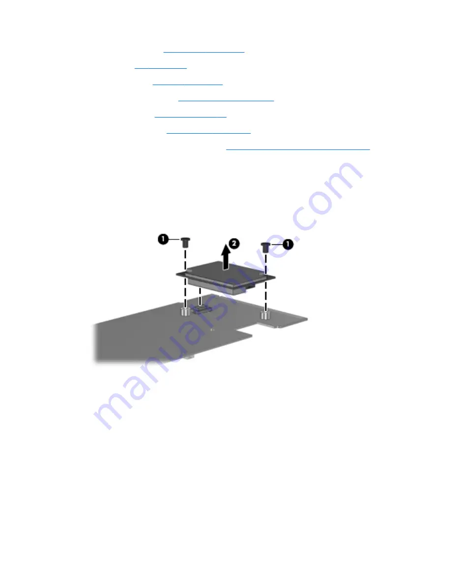
Remove the modem module:
1.
Turn the PC Card/audio board assembly upside down.
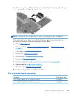
2.
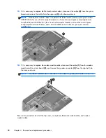
Remove the two Phillips PM2.5×3.0 screws
(1)
that secure the modem module to the PC Card/
audio board assembly.
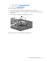
3.
Lift the modem module
(2)
straight up and remove it.
Reverse this procedure to install the modem module.
98
Chapter 4 Removal and replacement procedures
Summary of Contents for Compaq 6710b
Page 4: ...iv Safety warning notice ...
Page 9: ...Index 164 ix ...
Page 10: ...x ...
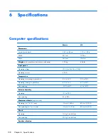
Page 34: ...Computer major components 24 Chapter 3 Illustrated parts catalog ...
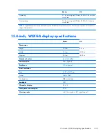
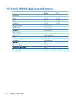
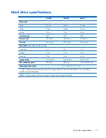
Page 124: ...Startup time 15 seconds Stop time 6 seconds 114 Chapter 6 Specifications ...
Page 178: ......


