Reverse this procedure to install the WLAN module.
46
Chapter 4 Removal and replacement procedures
Page 1: ...HP 430 and HP 431 Notebook PC and Compaq 435 and Compaq 436 Notebook PC Maintenance and Service Guide ...
Page 2: ...s Microsoft and Windows are U S registered trademarks of Microsoft Corporation SD Logo is a trademark of its proprietor The information contained herein is subject to change without notice The only warranties for HP products and services are set forth in the express warranty statements accompanying such products and services Nothing herein should be construed as constituting an additional warranty...
Page 3: ...w another hard surface such as an adjoining optional printer or a soft surface such as pillows or rugs or clothing to block airflow Also do not allow the AC adapter to contact the skin or a soft surface such as pillows or rugs or clothing during operation The device and the AC adapter comply with the user accessible surface temperature limits defined by the International Standard for Safety of Inf...
Page 4: ...iv Safety warning notice ...
Page 5: ...Computer major components 20 Cable Kit 25 Display assembly subcomponents 26 Mass storage devices 28 Miscellaneous parts 29 Plastics Kit 30 Sequential part number listing 30 4 Removal and replacement procedures 36 Preliminary replacement requirements 36 Tools required 36 Service considerations 36 Plastic parts 36 Cables and connectors 36 Drive handling 37 Grounding guidelines 37 Electrostatic disch...
Page 6: ...ctor cable 79 RTC battery 81 Fan heat sink assembly 83 Processor 89 5 Setup Utility BIOS and System Diagnostics 92 Using Setup Utility 92 Starting Setup Utility 92 Changing the language of Setup Utility 92 Navigating and selecting in Setup Utility 93 Displaying system information 93 Restoring factory settings in Setup Utility 94 Exiting Setup Utility 94 Updating the BIOS 94 Determining the BIOS ve...
Page 7: ...uter boot order 103 Backing up and recovering your information 104 Using Windows Backup and Restore 105 Using Windows system restore points 105 When to create restore points 105 Create a system restore point 106 Restore to a previous date and time 106 8 Power cord set requirements 107 Requirements for all countries 107 Requirements for specific countries and regions 108 9 Recycling 109 Battery 109...
Page 8: ...viii ...
Page 9: ...B L2 cache 1066 MHz FSB 25 W 3 6 gigatransfers second AMD Phenom II N660 Triple Core 3 00 GHz processor 2 0 MB L2 cache 1333 MHz FSB 35 W 3 6 gigatransfers second AMD Phenom II N650 Dual Core 2 60 GHz processor 2 0 MB L2 cache 1333 MHz FSB 25 W 3 6 gigatransfers second AMD Athlon II N370 Dual Core 2 50 GHz processor 1 0 MB L2 cache 1066 MHz FSB 35 W 3 2 gigatransfers second AMD Athlon II N350 Dual...
Page 10: ...second AMD E350 1 60 GHz processor Dual Core 18 W AMD E240 1 50 GHz processor Single Core 18 W Intel Dual Core i5 2540M 2 60 GHz processor SC turbo up to 3 30 GHz 3 0 MB L3 cache 35 W Intel Dual Core i5 2520M 2 50 GHz processor SC turbo up to 3 20 GHz 3 0 MB L3 cache 35 W Intel Dual Core i5 2410M 2 30 GHz processor SC turbo up to 2 90 GHz 3 0 MB L3 cache 35 W Intel Dual Core i3 2330M 2 20 GHz proc...
Page 11: ...0 MB L2 cache 800 MHz FSB Intel Celeron SC C925 2 30 GHz processor 1 0 MB L2 cache 800 MHz FSB Intel Celeron SC C900 2 20 GHz processor 1 0 MB L2 cache 800 MHz FSB Intel Celeron SC B810 1 60 GHz processor 1 0 MB L2 cache 800 MHz FSB Chipset AMD A50M fusion controller hub FCH on computer models equipped with a graphics subsystem with UMA memory Northbridge ATI RS880M on computer models equipped wit...
Page 12: ...900 MHz 4 PCs 64 bit S3 package muxless switchable Unified Memory Architecture UMA internal graphics ATI Mobility Radeon HD 4250 support for DX10 64 bit muxless switchable Internal graphics Intel HD Graphics Discrete graphics AMD Radeon HD 6370M Graphics with 512 MB of discrete video memory 64M 16 DDR3 900 MHz 4 PCs Switchable discrete graphics not supported on computer models equipped with Window...
Page 13: ...accessible upgradable memory module slots Supports dual channel memory Supports up to 8192 GB of system RAM DDR3 1333 MHz Supports the following configurations 8192 MB total system memory 4096 2 not supported on a 32 bit operating system 4096 MB total system memory 4096 1 or 2048 2 not supported with Windows 7 Starter OS 3072 MB total system memory 2048 1 1024 1 not supported with Windows 7 Starte...
Page 14: ... and CD RW Super Multi Double Layer Combo Drive with LightScribe Audio and video Single digital microphone HD audio Presario branded Altec Lansing speakers Supports Microsoft Premium requirements HP VGA webcam select models only fixed no tilt with activity LED 640 480 by 24 frames per second Ethernet Integrated 10 100 network interface card NIC Integrated 10 100 1000 network interface card NIC on ...
Page 15: ... 2 2 WiFi and Bluetooth 3 0 HS Combo Adapter Realtek 8188GN 802 11b g n 1 1 WiFi Adapter External media card HP Multi Format Digital Media Reader supports the following digital card formats MultiMediaCard MMC Secure Digital SD Memory Card Secure Digital High Capacity SDHC Memory Card Ports 3 pin AC power Audio in mono microphone Audio out stereo headphone HDMI version 1 4 supporting 1920 1200 60Hz...
Page 16: ...lug support 3 wire plug with ground pin supports 3 pin DC connector 90 W PFC RC V HP Smart AC adapter with localized cable plug support 3 wire plug with ground pin supports 3 pin DC connector 65 W RC V EM HP Smart AC adapter with localized cable plug support 3 wire plug with ground pin supports 3 pin DC connector Support for the following batteries 6 cell 55 Whr 2 55 Ah Li ion battery 6 cell 47 Wh...
Page 17: ...uipped with an Intel processor Preinstalled Windows 7 Home Basic 64 and 32 bit Windows 7 Home Premium 64 bit Windows 7 Professional 64 bit Windows 7 Starter 32 bit FreeDOS Serviceability End user replaceable parts AC adapter Battery Hard drive Memory modules 2 Optical drive WLAN module 9 ...
Page 18: ...e power is on NOTE The display switch is not visible from the outside of the computer 3 WLAN antennas 2 select models only Send and receive wireless signals to communicate with WLANs 4 Webcam light On The webcam is in use 5 Webcam Records video and captures still photographs To use the webcam select Start All Programs CyberLink YouCam CyberLink YouCam 10 Chapter 2 External component identification...
Page 19: ...ription Power button When the computer is off press the button to turn on the computer When the computer is on press the button briefly to initiate Sleep When the computer is in the Sleep state press the button briefly to exit Sleep When the computer is in Hibernation press the button briefly to exit Hibernation If the computer has stopped responding and Windows shutdown procedures are ineffective...
Page 20: ...2 fn key Displays system information when pressed in combination with the esc key 3 Windows logo key Displays the Windows Start menu 4 Windows applications key Displays a shortcut menu for items beneath the pointer 5 Action keys Execute frequently used system functions 12 Chapter 2 External component identification ...
Page 21: ...ps lock light On Caps lock in on 3 Power light On The computer is on Blinking The computer is in the Sleep state Off The computer is off or in Hibernation 4 Wireless light White An integrated wireless device such as a WLAN device and or a Bluetooth device is on Amber All wireless devices are off Lights 13 ...
Page 22: ...off button Turns the TouchPad on and off 3 TouchPad zone Moves the pointer and selects or activates items on the screen 4 Left TouchPad button Functions like the left button on an external mouse 5 Right TouchPad button Functions like the right button on an external mouse 14 Chapter 2 External component identification ...
Page 23: ...ices 6 Audio in microphone jack Connects an optional computer headset microphone stereo array microphone or monaural microphone 7 Audio out headphone jack Produce sound when connected to optional powered stereo speakers headphones ear buds a headset or television audio WARNING To reduce the risk of personal injury adjust the volume before putting on headphones earbuds or a headset For additional s...
Page 24: ... 3 USB ports 2 Connect optional USB devices 4 Power connector Connects an AC adapter 5 Battery AC adapter light White The computer is connected to external power and the battery is fully charged Amber A battery is charging Blinking amber The battery has reached a low battery level or there is a battery error When a battery reaches a critical battery level the battery light begins blinking rapidly ...
Page 25: ...utine operation 4 Hard drive bay Holds the hard drive 5 Memory module compartment Contains the wireless LAN WLAN device and the memory module slots CAUTION To prevent an unresponsive system replace the wireless module only with a wireless module authorized for use in the computer by the governmental agency that regulates wireless devices in your country or region If you replace the module and then...
Page 26: ...computer serial number and model description provided on the service tag Item Description Function 1 Product name This is the product name affixed to the front of the computer 2 Serial number s n This is an alphanumeric identifier that is unique to each product 18 Chapter 3 Illustrated parts catalog ...
Page 27: ... provides specific information about the product s hardware components The part number helps a service technician to determine what components and parts are needed 4 Warranty period This number describes the duration of the warranty period for the computer Service tag 19 ...
Page 28: ...Computer major components 20 Chapter 3 Illustrated parts catalog ...
Page 29: ...81 For use in the United States 646125 001 3 Top cover includes TouchPad and TouchPad cable In pewter finish for use with all computer models 646667 001 In charcoal gray finish for use only with Compaq 435 and Compaq 436 computer models 645963 001 4 Power button board includes cable 646171 001 5 TouchPad button board includes bracket and cable 646172 001 Cable Kit includes 645968 001 6a TouchPad c...
Page 30: ...bsystem with discrete video memory and 512 MB of graphics subsystem memory 646670 001 For use only with computer models equipped with an Intel Pentium processor and a graphics subsystem with UMA video memory 646669 001 For use only with computer models equipped with an Intel Celeron or Core 2 Duo processor and a graphics subsystem with UMA video memory 646668 001 12 RTC battery includes cable and ...
Page 31: ...L2 cache 1066 MHz FSB 25 W 572930 001 Intel Core 2 Duo T6670 2 20 GHz processor 2 0 MB L3 cache 800 MHz FSB 572927 001 Intel Celeron DC T3500 2 10 GHz processor 1 0 MB L2 cache 800 MHz FSB 625830 001 Intel Celeron DC T3300 2 00 GHz processor 1 0 MB L2 cache 800 MHz FSB 592399 001 Intel Celeron SC B950 2 10 GHz processor 1 0 MB L2 cache 800 MHz FSB 653338 001 Intel Celeron SC B940 2 00 GHz processo...
Page 32: ...and 4 rubber feet 646660 001 16 Battery 6 cell 55 Whr 2 55 Ah Li ion battery 593554 001 6 cell 47 Whr 2 20 Ah Li ion battery 593553 001 17 Optical drive select models only includes bezel and bracket Blu ray Disc ROM with SuperMulti DVD R RW Double Layer Drive with LightScribe 645989 001 DVD RW and CD RW Super Multi Double Layer Combo Drive with LightScribe 645988 001 18 Hard drive 2 5 in 7 0 mm SA...
Page 33: ...alink 5390GN 802 11b g n 1 1 WiFi Adapter 630703 001 Realtek 8188BC8 802 11a b g n 2 2 WiFi and Bluetooth 3 0 HS Combo Adapter 602993 001 Realtek 8188GN 802 11b g n 1 1 WiFi Adapter 640926 001 Cable Kit Item Component Spare part number Cable Kit includes 645968 001 1 TouchPad cable 2 Optical drive connector cable 3 Hard drive connector cable Cable Kit 25 ...
Page 34: ...rt number 1 Display bezel In pewter finish for use with all computer models 646661 001 In charcoal gray finish for use only with Compaq 435 and Compaq 436 computer models 645964 001 2 Display hinge covers 2 645971 001 26 Chapter 3 Illustrated parts catalog ...
Page 35: ... 001 6 Display Cable Kit includes display panel cable and webcam microphone module cable 645967 001 7 Antenna Kit includes left and right wireless antenna cables and transceivers 645966 001 8 Display enclosure In pewter finish for use with all computer models 646659 001 In charcoal gray finish for use only with Compaq 435 and Compaq 436 computer models 645959 001 Display Screw Kit not illustrated ...
Page 36: ...001 For use with all computer models 750 GB 5400 rpm 634250 001 640 GB 5400 rpm 603785 001 500 GB 7200 rpm 634925 001 500 GB 5400 rpm 634638 001 320 GB 7200 rpm 641672 001 and 634862 001 320 GB 5400 rpm 645193 001 and 622643 001 250 GB 7200 rpm 634861 001 Hard Drive Hardware Kit includes 645969 001 2 Hard drive bracket Screws not illustrated 3 Optical drive select models only includes bezel and br...
Page 37: ...rt AC adapter 609947 001 65 W RC V EM HP Smart AC adapter 609948 001 65 W RC V HP Smart AC adapter 609939 001 Power cord 3 pin black 1 83 m For use in Argentina 490371 D01 For use in Australia 490371 011 For use in Brazil 490371 202 For use in India 490371 D61 For use in North America 490371 001 For use in the People s Republic of China 490371 AA1 For use in South Korea 490371 AD1 For use in Taiwa...
Page 38: ...3 m 490371 201 Power cord for use in Thailand 3 pin black 1 83 m 490371 202 Power cord for use in Brazil 3 pin black 1 83 m 490371 AA1 Power cord for use in the People s Republic of China 3 pin black 1 83 m 490371 AB1 Power cord for use in Taiwan 3 pin black 1 83 m 490371 AD1 Power cord for use in South Korea 3 pin black 1 83 m 490371 D01 Power cord for use in Argentina 3 pin black 1 83 m 490371 D...
Page 39: ...SB 35 W 3 2 gigatransfers second 616343 001 AMD Athlon II P340 Dual Core 2 20 GHz processor 1 0 MB L2 cache 1066 MHz FSB 25 W 3 2 gigatransfers second 621565 001 2 GB memory module PC3 10600 1333 MHz 621569 001 4 GB memory module PC3 10600 1333 MHz 622643 001 320 GB 5400 rpm hard drive for use with all computer models 2 5 in 7 0 mm SATA does not include hard drive connector cable hard drive bracke...
Page 40: ...635499 001 AMD E240 1 50 GHz processor Single Core 18 W 635499 001 AMD E240 1 50 GHz processor Single Core 18 W 635500 001 Intel Pentium P6300 2 26 GHz processor 3 0 MB L3 cache dual core 35 W includes replacement thermal material 636634 001 AMD Sempron V160 Single Core 2 40 GHz processor 512 KB L2 cache 1066 MHz FSB 25 W 3 2 gigatransfers second 636635 001 AMD Athlon II P360 Dual Core 2 30 GHz pr...
Page 41: ...ers and cable 645981 001 Plastics Kit includes hard drive compartment cover and memory module wireless module compartment cover NOTE See Plastics Kit on page 30 for more Plastics Kit spare part information 645984 001 14 0 in HD LED BrightView display assembly in charcoal gray finish for use only with Compaq 435 and Compaq 436 models includes webcam microphone and wireless antenna transceivers and ...
Page 42: ...ith all computer models includes webcam microphone and wireless antenna transceivers and cables 646666 001 14 0 in HD LED AntiGlare display assembly in pewter finish for use with all computer models includes webcam microphone and wireless antenna transceivers and cables 646667 001 Top cover in pewter finish for use with all computer models includes power button board and cable and TouchPad and Tou...
Page 43: ...sor and a graphics subsystem with UMA memory includes replacement thermal material 647317 001 Fan heat sink assembly for use only with computer models equipped with an AMD E350 or E240 processor and a graphics subsystem with discrete memory includes replacement thermal material 647318 001 Fan heat sink assembly for use only with computer models equipped with an AMD Athlon II Phenom II Turion II or...
Page 44: ...sembly can damage plastic parts Use care when handling the plastic parts Apply pressure only at the points designated in the maintenance instructions Cables and connectors CAUTION When servicing the computer be sure that cables are placed in their proper locations during the reassembly process Improper cable placement can damage the computer Cables must be handled with extreme care to avoid damage...
Page 45: ...posing an internal hard drive to products that have magnetic fields such as monitors or speakers Avoid exposing a drive to temperature extremes or liquids If a drive must be mailed place the drive in a bubble pack mailer or other suitable form of protective packaging and label the package FRAGILE Grounding guidelines Electrostatic discharge damage Electronic components are sensitive to electrostat...
Page 46: ...following table shows how humidity affects the electrostatic voltage levels generated by different activities CAUTION A product can be degraded by as little as 700 V Typical electrostatic voltage levels Relative humidity Event 10 40 55 Walking across carpet 35 000 V 15 000 V 7 500 V Walking across vinyl floor 12 000 V 5 000 V 3 000 V Motions of bench worker 6 000 V 800 V 400 V Removing DIPS from p...
Page 47: ...nd and that proper materials are selected to avoid static charging When grounding is not possible use an ionizer to dissipate electric charges Workstation guidelines Follow these grounding workstation guidelines Cover the workstation with approved static shielding material Use a wrist strap connected to a properly grounded work surface and use properly grounded tools and equipment Use conductive f...
Page 48: ... between the operator and ground To be effective the conductive must be worn in contact with the skin The following grounding equipment is recommended to prevent electrostatic damage Antistatic tape Antistatic smocks aprons and sleeve protectors Conductive bins and other assembly or soldering aids Nonconductive foam Conductive tabletop workstations with ground cords of one megohm resistance Static...
Page 49: ...rew and size and location during removal and replacement Service tag When ordering parts or requesting information provide the computer serial number and model number provided on the service tag Item Component Description 1 Product name This is the product name affixed to the front of the computer 2 Serial number s n This is an alphanumeric identifier that is unique to each product Component repla...
Page 50: ...a service technician determine what components and parts are needed 4 Warranty period This number describes the duration of the warranty period for the computer Computer feet The computer feet are adhesive backed rubber pads There are 4 rubber feet that attach to the base enclosure in the locations illustrated below 42 Chapter 4 Removal and replacement procedures ...
Page 51: ...onnect the power from the computer by first unplugging the power cord from the AC outlet and then unplugging the AC adapter from the computer Remove the battery 1 Slide the battery release latch 1 to release the battery 2 Pivot the front edge of the battery 2 up and back 3 Remove the battery 3 from the computer To insert the battery 1 Align the tabs on the rear edge of the battery with the notches...
Page 52: ...he module to restore device functionality and then contact technical support Before removing the WLAN module follow these steps 1 Shut down the computer If you are unsure whether the computer is off or in Hibernation turn the computer on and then shut it down through the operating system 2 Disconnect all external devices connected to the computer 3 Disconnect the power from the computer by first u...
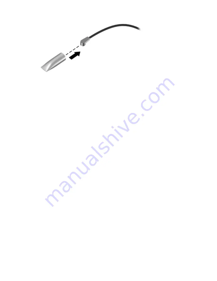
Page 53: ... WLAN module Main terminal The 2 WLAN antenna cable is connected to the WLAN module Aux terminal 5 Remove the Phillips PM2 0 3 0 screw 2 that secures the WLAN module to the system board The WLAN module tilts up 6 Remove the WLAN module by pulling the module away from the slot at an angle 3 NOTE The WLAN module is designed with a notch 4 to prevent incorrect installation into the WLAN module socket...
Page 54: ...Reverse this procedure to install the WLAN module 46 Chapter 4 Removal and replacement procedures ...
Page 55: ... to the computer 3 Disconnect the power from the computer by first unplugging the power cord from the AC outlet and then unplugging the AC adapter from the computer 4 Remove the battery see Battery on page 43 5 Remove the memory module wireless module compartment cover see WLAN module on page 44 Remove the memory module 1 Spread the retaining tabs 1 on each side of the memory module slot to releas...
Page 56: ...and 634862 001 320 GB 5400 rpm 645193 001 and 622643 001 250 GB 7200 rpm 634861 001 Before removing the hard drive follow these steps 1 Shut down the computer If you are unsure whether the computer is off or in Hibernation turn the computer on and then shut it down through the operating system 2 Disconnect all external devices connected to the computer 3 Disconnect the power from the computer by f...
Page 57: ...ard drive compartment cover The hard drive compartment cover is available in the Plastics Kit spare part number 645981 001 4 Disconnect the hard drive connector cable 1 from the system board 5 Remove the four Phillips PM 2 5 6 0 screws 2 that secure the hard drive to the computer Component replacement procedures 49 ...
Page 58: ...ary to replace the hard drive screws 1 the hard drive bracket 2 or the hard drive connector cable 3 remove and replace the components Reverse this procedure to reassemble and install the hard drive 50 Chapter 4 Removal and replacement procedures ...
Page 59: ...evices connected to the computer 3 Disconnect the power from the computer by first unplugging the power cord from the AC outlet and then unplugging the AC adapter from the computer 4 Remove the battery see Battery on page 43 5 Remove the memory module wireless module compartment cover see WLAN module on page 44 6 Remove the hard drive compartment cover see Hard drive on page 48 Remove the optical ...
Page 60: ... drive with the rear panel toward you 5 Remove the two Phillips PM2 0 3 0 screws 1 that secure the bracket to the optical drive 6 Remove the optical drive bracket 2 Reverse this procedure to reassemble and install the optical drive 52 Chapter 4 Removal and replacement procedures ...
Page 61: ...ure whether the computer is off or in Hibernation turn the computer on and then shut it down through the operating system 2 Disconnect all external devices connected to the computer 3 Disconnect the power from the computer by first unplugging the power cord from the AC outlet and then unplugging the AC adapter from the computer 4 Remove the battery see Battery on page 43 5 Remove the memory module...
Page 62: ...puter on its left side 3 Partially open the computer 4 Insert a screw driver or similar thin tool into the keyboard release hole and then press on the back of the keyboard until the keyboard disengages from the computer 5 Turn the computer right side up with the front toward you 54 Chapter 4 Removal and replacement procedures ...
Page 63: ... rests upside down on the palm rest 7 Release the zero insertion force ZIF connector 1 to which the keyboard cable is attached and then disconnect the keyboard cable 2 from the system board 8 Remove the keyboard Reverse this procedure to install the keyboard Component replacement procedures 55 ...
Page 64: ...puter by first unplugging the power cord from the AC outlet and then unplugging the AC adapter from the computer 4 Remove the battery see Battery on page 43 and then remove the following components Memory module wireless module compartment cover see WLAN module on page 44 Hard drive see Hard drive on page 48 Keyboard see Keyboard on page 53 NOTE When replacing the top cover be sure that the follow...
Page 65: ...cover to the computer 4 Remove the two Phillips PM2 5 10 0 screws 1 and the four Phillips PM2 0 3 0 screws 2 that secure the top cover to the computer 5 Turn the computer right side up with the front toward you 6 Open the computer Component replacement procedures 57 ...
Page 66: ...utton board cable 1 included with the power button board spare part kit spare part number 646129 001 TouchPad button board cable 2 included with the TouchPad button board spare part kit spare part number 646130 001 TouchPad cable 3 included in the Cable Kit spare part number 646119 001 58 Chapter 4 Removal and replacement procedures ...
Page 67: ...secure the top cover to the computer 9 Lift the rear edge of the top cover 1 until the left and right sides disengage from the base enclosure 10 Remove the top cover 2 Reverse this procedure to install the top cover Component replacement procedures 59 ...
Page 68: ...puter by first unplugging the power cord from the AC outlet and then unplugging the AC adapter from the computer 4 Remove the battery see Battery on page 43 and then remove the following components Memory module wireless module compartment cover see WLAN module on page 44 Hard drive see Hard drive on page 48 Keyboard see Keyboard on page 53 Top cover see Top cover on page 56 Remove the power butto...
Page 69: ...computer on and then shut it down through the operating system 2 Disconnect all external devices connected to the computer 3 Disconnect the power from the computer by first unplugging the power cord from the AC outlet and then unplugging the AC adapter from the computer 4 Remove the battery see Battery on page 43 and then remove the following components Memory module wireless module compartment co...
Page 70: ...he top cover The TouchPad board cable and the TouchPad button board cable are attached to the top cover with double sided tape 3 Remove the four Phillips PM2 0 4 0 screws 3 that secure the TouchPad button board to the top cover 4 Remove the TouchPad button board 4 Reverse this procedure to install the TouchPad button board and cable 62 Chapter 4 Removal and replacement procedures ...
Page 71: ...he computer 4 Remove the battery see Battery on page 43 and then remove the following components Memory module wireless module compartment cover see WLAN module on page 44 Hard drive see Hard drive on page 48 Keyboard see Keyboard on page 53 Top cover see Top cover on page 56 Remove the speakers 1 Disconnect the speaker cable 1 from the system board 2 Release the speaker cables 2 from the clips bu...
Page 72: ...5 Remove the speakers 6 Reverse this procedure to install the speakers 64 Chapter 4 Removal and replacement procedures ...
Page 73: ...mputer 3 Disconnect the power from the computer by first unplugging the power cord from the AC outlet and then unplugging the AC adapter from the computer 4 Remove the battery see Battery on page 43 and then remove the following components Memory module wireless module compartment cover see WLAN module on page 44 Hard drive see Hard drive on page 48 Keyboard see Keyboard on page 53 Top cover see T...
Page 74: ... first unplugging the power cord from the AC outlet and then unplugging the AC adapter from the computer 4 Remove the battery see Battery on page 43 and then remove the following components Memory module wireless module compartment cover see WLAN module on page 44 Hard drive see Hard drive on page 48 Keyboard see Keyboard on page 53 Top cover see Top cover on page 56 Speakers see Speakers on page ...
Page 75: ...the front toward you 6 Open the computer 7 Release the power connector cable 1 from the clips and routing channel built into the base enclosure 8 Remove the two Phillips PM2 5 5 0 screws 2 that secure the power connector and bracket to the computer 9 Remove the power connector bracket 3 Component replacement procedures 67 ...
Page 76: ...AntiGlare in charcoal gray finish 647607 001 BrightView in charcoal gray finish 645984 001 Before removing the display assembly follow these steps 1 Shut down the computer If you are unsure whether the computer is off or in Hibernation turn the computer on and then shut it down through the operating system 2 Disconnect all external devices connected to the computer 3 Disconnect the power from the ...
Page 77: ... cable on page 66 Remove the display assembly 1 Disconnect the display panel cable 1 from the system board 2 Release the wireless antenna cables from the clips 2 built into the base enclosure CAUTION Support the display assembly when removing the following screws Failure to support the display assembly can result in damage to the display assembly and other computer components 3 Remove the four Phi...
Page 78: ...re part number 645976 001 b Flex the inside edges of the top edge 1 the left and right sides 2 and the bottom edge 3 of the display bezel until the bezel disengages from the display enclosure c Remove the display bezel 4 The display bezel is available using the following spare part numbers 646661 001 In pewter finish for use with all computer models 645964 001 In charcoal gray finish for use only ...
Page 79: ...ure with double sided tape b Disconnect the module cable 2 from the module c Remove the webcam microphone module 3 The webcam microphone module is available using spare part number 646138 001 7 If it is necessary to replace the hinge covers a Remove the two Phillips PM2 5 5 0 1 screws that secure the hinge covers to the display enclosure Component replacement procedures 71 ...
Page 80: ...g spare part number 645971 001 8 If it is necessary to replace the display panel a Remove the two Phillips PM2 5 4 0 screws 1 and four Phillips PM2 5 5 0 screws 2 that secure the display panel to the display enclosure 72 Chapter 4 Removal and replacement procedures ...
Page 81: ...onnect the display panel cable 2 from the display panel d Remove the display panel The display panel is available using the following spare part numbers 646674 001 14 0 in HD LED AntiGlare display panel 645987 001 14 0 in HD LED BrightView display panel 9 If it is necessary to replace the display hinges a Remove the four Phillips PM2 0 3 0 screws 1 that secure the display hinges to the display pan...
Page 82: ...abs 1 built into the display enclosure shielding that secure the display panel cable to the display enclosure b Release the display panel cable from the clips 2 built into the display enclosure c Remove the display panel cable 3 The display panel cable includes the webcam microphone module cable and is available in the Display Cable Kit spare part number 645967 001 74 Chapter 4 Removal and replace...
Page 83: ... the display enclosure with double sided tape b Release the wireless antenna cable from the clips 2 built into the display enclosure c Remove the wireless antenna cable and transceiver 3 The wireless antenna cable and transceiver are available in the Antenna Kit spare part number 645966 001 Reverse this procedure to reassemble and install the display assembly Component replacement procedures 75 ...
Page 84: ...cs subsystem with UMA video memory 646671 001 For use only with computer models equipped with an Intel Pentium processor a graphics subsystem with discrete video memory and 512 MB of graphics subsystem memory 646670 001 For use only with computer models equipped with an Intel Pentium processor and a graphics subsystem with UMA video memory 646669 001 For use only with computer models equipped with...
Page 85: ...acement system board Memory module see Memory module on page 47 RTC battery see RTC battery on page 81 Fan heat sink assembly see Fan heat sink assembly on page 83 Processor see Processor on page 89 Remove the system board 1 Disconnect the optical drive connector cable from the system board 2 Remove the Phillips PM2 5 6 0 screw 1 that secures the system board to the base enclosure 3 Lift the right...
Page 86: ...oard The thermal material must be thoroughly cleaned from the surfaces of the system board 1 and the heat sink 2 attached to the base enclosure each time the system board is removed Replacement thermal material is included with all base enclosure and system board spare part kits Reverse this procedure to install the system board 78 Chapter 4 Removal and replacement procedures ...
Page 87: ...en unplugging the AC adapter from the computer 4 Remove the battery see Battery on page 43 and then remove the following components WLAN module see WLAN module on page 44 Keyboard see Keyboard on page 53 Top cover see Top cover on page 56 Speakers see Speakers on page 63 USB board see USB board on page 65 Power connector cable see Power connector cable on page 66 Display assembly see Display assem...
Page 88: ...3 Remove the optical drive connector 3 from the base enclosure Reverse this procedure to install the optical drive connector cable 80 Chapter 4 Removal and replacement procedures ...
Page 89: ... the AC outlet and then unplugging the AC adapter from the computer 4 Remove the battery see Battery on page 43 and then remove the following components WLAN module see WLAN module on page 44 Keyboard see Keyboard on page 53 Top cover see Top cover on page 56 Speakers see Speakers on page 63 USB board see USB board on page 65 Power connector cable see Power connector cable on page 66 Display assem...
Page 90: ...tery 2 from the system board The RTC battery is attached to the system board with double sided tape 4 Remove the RTC battery Reverse this procedure to install the RTC battery 82 Chapter 4 Removal and replacement procedures ...
Page 91: ...cs subsystem with UMA video memory 646181 001 For use only with computer models equipped with an Intel Celeron or Core 2 processor and a graphics subsystem with UMA video memory 646184 001 NOTE To properly ventilate the computer allow at least 7 6 cm 3 in of clearance on the left side of the computer The computer uses an electric fan for ventilation The fan is controlled by a temperature sensor an...
Page 92: ...ve screws 1 that secure the fan heat sink assembly to the system board NOTE The number of screws used to secure the fan heat sink assembly to the system board varies by computer model NOTE Due to the adhesive quality of the thermal material located between the heat sink and system board components it may be necessary to move the heat sink from side to side to detach it 4 Remove the fan and heat si...
Page 93: ...quipped with an Intel Pentium processor and a graphics subsystem with discrete memory NOTE The following illustration shows the fan heat sink assembly removal process on a computer model equipped with an Intel Pentium processor and a graphics subsystem with UMA memory Component replacement procedures 85 ...
Page 94: ...urfaces of the heat sink and the system board components each time the heat sink is removed Replacement thermal material is included with the base enclosure fan heat sink assembly processor and system board spare part kits NOTE The following illustration shows the replacement thermal material locations on a computer model equipped with an AMD processor 86 Chapter 4 Removal and replacement procedur...
Page 95: ... with an Intel Pentium processor and a graphics subsystem with discrete memory Thermal paste is used on the processor 1 and the heat sink section 2 that services it A thermal pad is used on the graphics subsystem chip 3 and the heat sink section 4 that services it NOTE The following illustration shows the replacement thermal material locations on a computer model equipped with an Intel Pentium pro...
Page 96: ... shows the replacement thermal material locations on a computer model equipped with an Intel Celeron processor Thermal paste is used on the processor 1 and the heat sink section 2 that services it A thermal pad is used on the Northbridge chip 3 and the heat sink section 4 that services it Reverse this procedure to reassemble and install the fan heat sink assembly 88 Chapter 4 Removal and replaceme...
Page 97: ... MB L2 cache 1066 MHz FSB 35 W 3 6 gigatransfers second 634691 001 AMD Sempron V160 Single Core 2 40 GHz processor 512 KB L2 cache 1066 MHz FSB 25 W 3 2 gigatransfers second 636634 001 AMD Sempron V140 Single Core 2 30 GHz processor 512 KB L2 cache 1066 MHz FSB 25 W 3 2 gigatransfers second 616333 001 AMD E350 1 60 GHz processor Dual Core 18 W 635498 001 AMD E240 1 50 GHz processor Single Core 18 ...
Page 98: ...ough the operating system 2 Disconnect all external devices connected to the computer 3 Disconnect the power from the computer by first unplugging the power cord from the AC outlet and then unplugging the AC adapter from the computer 4 Remove the battery see Battery on page 43 and then remove the following components WLAN module see WLAN module on page 44 Keyboard see Keyboard on page 53 Top cover...
Page 99: ...en remove it NOTE The gold triangle 3 on the processor must be aligned with the triangle icon 4 embossed on the processor socket when you install the processor Reverse this procedure to install the processor Component replacement procedures 91 ...
Page 100: ...t can be used with Setup Utility only if USB legacy support is enabled To start Setup Utility follow these steps 1 Turn on or restart the computer and then press esc while the Press the ESC key for Startup Menu message is displayed at the bottom of the screen 2 Press f10 to enter Setup Utility Changing the language of Setup Utility 1 Start Setup Utility 2 Use the arrow keys to select System Config...
Page 101: ...er Setup Utility To exit Setup Utility menus choose one of the following methods To exit Setup Utility menus without saving your changes press the esc key and then follow the on screen instructions or Use the arrow keys to select Exit Exit Discarding Changes and then press enter To save your changes and exit Setup Utility menus press f10 and then follow the on screen instructions or Use the tab ke...
Page 102: ...and security settings are not changed when you restore the factory settings Exiting Setup Utility To exit Setup Utility and save your changes from the current session If the Setup Utility menus are not visible press esc to return to the menu display Then use the arrow keys to select Exit Exit Saving Changes and then press enter To exit Setup Utility without saving your changes from the current ses...
Page 103: ...n follow these instructions Do not disconnect power from the computer by unplugging the power cord from the AC outlet Do not shut down the computer or initiate Sleep or Hibernation Do not insert remove connect or disconnect any device cable or cord 1 Windows 7 Select Start Help and Support Maintain Windows XP Select Start Help and Support and then select the software and drivers update 2 Follow th...
Page 104: ...yzes the main computer components that are required to start the computer Run in test This test repeats the start up test and checks for intermittent problems that the start up test does not detect Hard disk test This test analyzes the physical condition of the hard drive and then checks all data in every sector of the hard drive If the test detects a damaged sector it attempts to move the data to...
Page 105: ... 5 A 65 W or 4 74 A 90 W Temperature Operating 5 C to 35 C 41 F to 95 F Nonoperating 20 C to 60 C 4 F to 140 F Relative humidity noncondensing Operating 10 to 90 Nonoperating 5 to 95 Maximum altitude unpressurized Operating 15 m to 3 048 m 50 ft to 10 000 ft Nonoperating 15 m to 12 192 m 50 ft to 40 000 ft NOTE Applicable product safety standards specify thermal limits for plastic surfaces The dev...
Page 106: ...n Number of colors Up to 16 8 million Contrast ratio 200 1 typical Brightness 200 nits typical Pixel resolution Pitch 0 197 0 197 mm Format 1366 768 Configuration RGB vertical stripe Backlight LED Character display 80 25 Total power consumption 2 0 W Viewing angle 65 horizontal 50 vertical typical 98 Chapter 6 Specifications ...
Page 107: ...rity Seek times typical read including setting Single track 1 5 ms 1 5 ms 1 5 ms Average read write 11 13 ms 11 13 ms 11 13 ms Maximum 22 ms 22 ms 22 ms Logical blocks 976 773 168 628 142 448 488 397 168 Disk rotational speed 5400 rpm 5400 rpm 5400 rpm Operating temperature 0 C to 60 C 32 F to 140 F 1 GB 1 billion bytes when referring to hard drive storage capacity Actual accessible capacity is le...
Page 108: ...er HP recommends that you use this software to create either a set of recovery discs or a recovery flash drive immediately after software setup If for some other reason you need to restore your system this can be achieved using the HP Recovery partition select models only without the need for recovery discs or a recovery flash drive To check for the presence of a recovery partition click Start rig...
Page 109: ... an external optical drive it must be connected directly to a USB port on the computer not to a USB port on an external device such as a USB hub Guidelines Purchase high quality DVD R DVD R DVD R DL or DVD R DL discs NOTE Read write discs such as CD RW DVD RW and double layer DVD RW discs are not compatible with the Recovery Manager software The computer must be connected to AC power during this p...
Page 110: ...ng Recovery Manager Recovery Manager restores only software that was preinstalled at the factory Software not provided with this computer must be downloaded from the manufacturer s Web site or reinstalled from the disc provided by the manufacturer Restoring using the dedicated recovery partition select models only When using the dedicated recovery partition there is an option to back up pictures m...
Page 111: ... 3 Press f9 at system bootup 4 Select the optical drive or the flash drive 5 Follow the on screen instructions Changing the computer boot order To change the boot order for recovery discs 1 Restart the computer 2 Press esc while the computer is restarting and then press f9 for boot options 3 Select Internal CD DVD ROM Drive from the boot options window To change the boot order for recovery flash d...
Page 112: ...ion periodically Before the computer is repaired or restored Before you add or modify hardware or software Guidelines Create system restore points using the Windows System Restore feature and periodically copy them to an optical disc or an external hard drive For more information on using system restore points refer to Using Windows system restore points Store personal files in the Documents libra...
Page 113: ...Windows settings Refer to Help and Support for more information Using Windows system restore points A system restore point allows you to save and name a snapshot of your hard drive at a specific point in time You can then recover back to that point if you want to reverse subsequent changes NOTE Recovering to an earlier restore point does not affect data files saved or e mails created since the las...
Page 114: ...tions Restore to a previous date and time To revert to a restore point created at a previous date and time when the computer was functioning optimally follow these steps 1 Select Start Control Panel System and Security System 2 In the left pane click System Protection 3 Click the System Protection tab 4 Click System Restore 5 Follow the on screen instructions 106 Chapter 7 Backup and recovery ...
Page 115: ... requirements are applicable to all countries and regions The length of the power cord set must be at least 1 5 m 5 0 ft and no more than 2 0 m 6 5 ft All power cord sets must be approved by an acceptable accredited agency responsible for evaluation in the country or region where the power cord set will be used The power cord sets must have a minimum current capacity of 10 amps and a nominal volta...
Page 116: ...g must be a two pole grounding type with a NEMA 5 15P 15 A 125 V or NEMA 6 15P 15 A 250 V configuration 3 The appliance coupler flexible cord and wall plug must bear a T mark and registration number in accordance with the Japanese Dentori Law The flexible cord must be Type VCT or VCTF 3 conductor 1 00 mm conductor size The wall plug must be a two pole grounding type with a Japanese Industrial Stan...
Page 117: ...nts handle them carefully NOTE Materials Disposal This HP product contains mercury in the backlight in the display assembly that might require special handling at end of life Disposal of mercury may be regulated because of environmental considerations For disposal or recycling information contact your local authorities or see the Electronic Industries Alliance EIA Web site at http www eiai org Thi...
Page 118: ...hat secure the display bezel to the display assembly 2 Lift up and out on the left and right inside edges 1 and the top and bottom inside edges 2 of the display bezel until the bezel disengages from the display assembly 3 Remove the display bezel 3 110 Chapter 9 Recycling ...
Page 119: ...ssembly to the display enclosure 6 Remove the display panel assembly 2 from the display enclosure 7 Turn the display panel assembly upside down 8 Remove all screws that secure the display panel frame to the display panel 9 Use a sharp edged tool to cut the tape 1 that secures the sides of the display panel to the display panel frame Display 111 ...
Page 120: ...splay panel 11 Remove the screws 1 that secure the backlight cover to the display panel 12 Lift the top edge of the backlight cover 2 and swing it outward 13 Remove the backlight cover 14 Turn the display panel right side up 112 Chapter 9 Recycling ...
Page 121: ...l 16 Turn the display panel upside down 17 Remove the backlight frame from the display panel WARNING The backlight contains mercury Exercise caution when removing and handling the backlight to avoid damaging this component and causing exposure to the mercury Display 113 ...
Page 122: ...panel 20 Remove the screws 2 that secure the LCD panel to the display rear panel 21 Release the LCD panel 3 from the display rear panel 22 Release the tape 4 that secures the LCD panel to the display rear panel 23 Remove the LCD panel 24 Recycle the LCD panel and backlight 114 Chapter 9 Recycling ...
Page 123: ...major components 20 computer part number 42 computer specifications 97 connectors service considerations 36 D Digital Media Slot 15 display assembly removal 68 spare part numbers 21 33 34 35 68 subcomponents 26 display bezel removal 70 spare part numbers 26 33 34 70 Display Cable Kit spare part number 27 33 74 display components 10 display enclosure spare part numbers 27 32 34 Display Hinge Kit sp...
Page 124: ... 13 14 webcam 10 wireless 13 M mass storage device precautions 37 removal 48 spare part numbers 28 48 memory module product description 5 removal 47 spare part numbers 24 31 32 47 memory module compartment 17 memory module wireless module compartment cover illustrated 30 removal 44 microphone location 11 product description 6 microphone jack 15 model name 1 monitor port 15 N network jack 15 O oper...
Page 125: ... spare part number 22 33 63 speakers locations 10 removal 63 spare part number 22 33 63 specifications computer 97 display 98 hard drive 99 system board removal 76 spare part numbers 22 34 35 76 System Diagnostics 92 T tools required 36 top cover removal 56 spare part numbers 21 33 34 56 TouchPad button 14 TouchPad button board removal 61 spare part number 21 34 61 TouchPad cable disconnection 58 ...