background image

d.

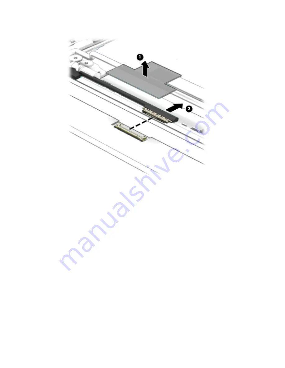
Disconnect the display panel cable (2) from the display panel.

e.

Remove the display panel.

The display panel is available using spare part number 783089-001.

11.

If it is necessary to replace the display panel cable:

a.

Release the display panel cable from the retention clip (1) built into the left hinge.

b.

Release the display panel cable from the retention clips (2) and routing channel built into the left 
side of the display enclosure.

c.

Release the grounding tape (3) that secures the display panel cable to the display enclosure.

48

Chapter 5   Removal and replacement procedures

Summary of Contents for Chromebook 11 G3

Page 1: ...HP Chromebook model numbers 11 2100 through 11 2199 and HP Chromebook 11 G3 Maintenance and Service Guide IMPORTANT This document is intended for HP authorized service providers only ...

Page 2: ...nying such products and services Nothing herein should be construed as constituting an additional warranty HP shall not be liable for technical or editorial errors or omissions contained herein Second Edition November 2014 First Edition September 2014 Document Part Number 780446 002 Product notice This guide describes features that are common to most models Some features may not be available on yo...

Page 3: ...w another hard surface such as an adjoining optional printer or a soft surface such as pillows or rugs or clothing to block airflow Also do not allow the AC adapter to contact the skin or a soft surface such as pillows or rugs or clothing during operation The device and the AC adapter comply with the user accessible surface temperature limits defined by the International Standard for Safety of Inf...

Page 4: ...iv Safety warning notice ...

Page 5: ... 13 Miscellaneous parts 14 Sequential part number listing 15 4 Removal and replacement preliminary requirements 19 Tools required 19 Service considerations 19 Plastic parts 19 Cables and connectors 19 Drive handling 20 Grounding guidelines 21 Electrostatic discharge damage 21 Packaging and transporting guidelines 22 Workstation guidelines 22 5 Removal and replacement procedures 24 Component replac...

Page 6: ...bly 43 6 Specifications 53 7 Statement of memory volatility 54 Nonvolatile memory usage 56 Questions and answers 58 Using HP Sure Start select models only 59 8 Power cord set requirements 60 Requirements for all countries 60 Requirements for specific countries and regions 60 9 Recycling 62 Index 63 vi ...

Page 7: ... 1600MHz Supports up to 2048 MB maximum on board system memory 4 pieces of 256 MB 16 Storage Supports 16 GB embedded MultiMedia Controller eMMC Audio and video Fixed integrated VGA webcam 640 480 by 30 frames per second Single digital microphone Two speakers HD audio Sensors Trusted platform module TPM Wireless Integrated wireless local area network WLAN options by way of wireless module Two built...

Page 8: ...equirements Supports a 3 cell 36 WHr 3 25 WHr Li Ion battery Supports a 65 W HP Smart AC adapter non PFC EM 4 5 mm and 45 W HP Smart AC adapter non PFC RC 4 5 mm AC adapter Operating system Preinstalled Google Chrome operating system Serviceability End user replaceable parts AC adapter 2 Chapter 1 Product description ...

Page 9: ...r country or region 3 Internal microphone Records sound 4 Webcam Records video captures still photographs and allows video conferences and online chat by means of streaming video 5 Webcam light On The webcam is in use 6 Internal display switch Turns off the display or initiates Sleep if the display is closed while the power is on NOTE The display switch is not visible from the outside of the compu...

Page 10: ...e press the button briefly to exit Sleep When the computer is on and you want to lock the screen press the power button until you see the sign in screen appear Pressing the power button during screen lock mode turns off the computer When the computer is on and you want to turn it off press and hold the power 4 Chapter 2 External component identification ...

Page 11: ...TouchPad Item Component Description 1 TouchPad zone Moves the on screen pointer and selects or activates items on the screen TouchPad 5 ...

Page 12: ...charged Amber The AC adapter is connected and the battery is charging Off The computer is using battery power 4 SIM slot select models only Supports a wireless subscriber identity module SIM 5 Memory card reader Reads optional memory cards that store manage share or access information To insert a card Hold the card label side up with connectors facing the slot insert the card into the slot and the...

Page 13: ...ter speakers are disabled NOTE Be sure that the device cable has 4 conductor connector that supports both audio out headphone and audio in microphone 3 USB 2 0 port Connect optional USB devices such as a keyboard mouse external drive printer scanner or USB hub 4 USB 3 0 charging powered port Connects an optional USB device such as a keyboard mouse external drive printer scanner or USB hub Standard...

Page 14: ...Bottom Item Component Description 1 Speakers 2 Produce sound 8 Chapter 2 External component identification ...

Page 15: ... and then follow the on screen instructions Locating the serial number model number product number and warranty information The serial number 1 model number 2 product number 3 and warranty information 4 are located on the bottom of the computer This information may be needed when travelling internationally or when contacting support Locating the serial number model number product number and warran...

Page 16: ...play assembly is spared at the subcomponent level only For more display assembly spare part information see Display assembly subcomponents on page 13 2 Keyboard top cover includes keyboard cable For use only on HP Chromebook 11 21xx computer models 10 Chapter 3 Illustrated parts catalog ...

Page 17: ... Belgium 788639 A41 For use in Canada 788639 DB1 For use in Denmark Finland and Norway 788639 DH1 For use in France 788639 051 For use in Germany 788639 041 For use in Italy 788639 061 For use in Japan 788639 291 For use in Latin America 788639 161 For use in the Netherlands 788639 B31 For use in Russia 788639 251 For use in Spain 788639 071 For use in Switzerland 788639 BG1 For use in the United ...

Page 18: ...cache 1333 MHz FSB 4 5 W and 4 0 GB of system memory 783074 001 Equipped with an Intel Celeron N2830 2 16 GHz SC turbo up to 2 41 GHz dual core processor 1 0 GB L2 cache 1333 MHz FSB 4 5 W and 2 0 GB of system memory 783073 001 12 Base enclosure For use only on HP Chromebook 11 21xx computer models equipped with WWAN capability In ocean turquoise finish 783078 001 In sweet yellow finish 783082 001...

Page 19: ...nly on HP Chromebook 11 21xx computer models in snow white finish 761965 001 For use only on HP Chromebook 11 21xx computer models in sweet yellow finish 761964 001 For use only on HP Chromebook 11 G3 computer models 773210 001 2 Webcam microphone module includes double sided adhesive 783088 001 3 Display panel 11 6 inch AG HD SVA LED 783089 001 Display assembly subcomponents 13 ...

Page 20: ...se only on HP Chromebook 11 21xx computer models in sweet yellow finish 761956 001 For use only on HP Chromebook 11 G3 computer models 794732 001 Miscellaneous parts Component Spare part number AC adapter 65 W HP Smart AC adapter non PFC EM 4 5 mm 714657 001 45 W HP Smart AC adapter non PFC RC 4 5 mm 741727 001 HP HDMI to VGA adapter 701943 001 HP RJ45 to USB adapter dongle 539614 001 Power cord F...

Page 21: ...ack 1 00 m 755530 291 Power cord for use in Japan 3 pin black 1 00 m 755530 D61 Power cord for use in India 3 pin black 1 00 m 761955 001 Display enclosure in ocean turquoise finish for use only on HP Chromebook 11 21xx computer models includes rubber padding and shielding 761956 001 Display enclosure in sweet yellow finish for use only on HP Chromebook 11 21xx computer models includes rubber padd...

Page 22: ...use only on HP Chromebook 11 21xx computer models not equipped with WWAN capability 783078 001 Base enclosure in ocean turquoise finish for use only on HP Chromebook 11 21xx computer models equipped with WWAN capability 783079 001 Base enclosure in sweet yellow finish for use only on HP Chromebook 11 21xx computer models not equipped with WWAN capability 783080 001 Base enclosure in sweet yellow f...

Page 23: ...11 21xx computer models in Canada includes keyboard cable 783090 DH1 Keyboard top cover for use only on HP Chromebook 11 21xx computer models in Denmark Finland and Norway includes keyboard cable 784191 001 Base enclosure for use only on HP Chromebook 11 G3 computer models not equipped with WWAN capability 784192 001 Base enclosure for use only on HP Chromebook 11 G3 computer models equipped with ...

Page 24: ...Switzerland includes keyboard cable 788639 DB1 Keyboard top cover for use only on HP Chromebook 11 G3 computer models in Canada includes keyboard cable 788639 DH1 Keyboard top cover for use only on HP Chromebook 11 G3 computer models in Denmark Finland and Norway includes keyboard cable 790939 001 System board equipped with an Intel Celeron N2840 2 16 GHz SC turbo up to 2 58 GHz dual core processo...

Page 25: ...ssembly can damage plastic parts Use care when handling the plastic parts Apply pressure only at the points designated in the maintenance instructions Cables and connectors CAUTION When servicing the computer be sure that cables are placed in their proper locations during the reassembly process Improper cable placement can damage the computer Cables must be handled with extreme care to avoid damag...

Page 26: ...e connector Before removing a diskette drive or optical drive be sure that a diskette or disc is not in the drive and be sure that the optical drive tray is closed Handle drives on surfaces covered with at least one inch of shock proof foam Avoid dropping drives from any height onto any surface After removing drive place it in a static proof bag Avoid exposing a drive to products that have magneti...

Page 27: ...ve these precautions Keep components in their electrostatic safe containers until you are ready to install them Before touching an electronic component discharge static electricity by using the guidelines described in this section Avoid touching pins leads and circuitry Handle electronic components as little as possible If you remove a component place it in an electrostatic safe container The foll...

Page 28: ... proper materials are selected to avoid static charging When grounding is not possible use an ionizer to dissipate electric charges Workstation guidelines Follow these grounding workstation guidelines Cover the workstation with approved static shielding material Use a wrist strap connected to a properly grounded work surface and use properly grounded tools and equipment Use conductive field servic...

Page 29: ... resistance between the operator and ground To be effective the conductive must be worn in contact with the skin The following grounding equipment is recommended to prevent electrostatic damage Antistatic tape Antistatic smocks aprons and sleeve protectors Conductive bins and other assembly or soldering aids Nonconductive foam Conductive computerop workstations with ground cords of one megohm resi...

Page 30: ...ded in the Rubber Kit available using the following spare part numbers 762581 001 For use only on HP Chromebook 11 21xx computer models in ocean turquoise finish 762583 001 For use only on HP Chromebook 11 21xx computer models in snow white finish 762582 001 For use only on HP Chromebook 11 21xx computer models in sweet yellow finish 773211 001 For use only on HP Chromebook 11 G3 computer models B...

Page 31: ...83090 071 For use in Germany 783090 041 For use in Switzerland 783090 BG1 For use in Italy 783090 061 For use in the United Kingdom 783090 031 For use in Japan 783090 291 For use in the United States 783090 001 For use only on HP Chromebook 11 G3 computer models For use in Belgium 788639 A41 For use in Latin America 788639 161 For use in Canada 788639 DB1 For use in the Netherlands 788639 B31 For ...

Page 32: ...top cover Remove the keyboard top cover 1 Remove the two rubber screw covers 1 NOTE The rubber screw covers are included in the Rubber Kit spare part numbers 762581 001 For use only on HP Chromebook 11 21xx computer models in ocean turquoise finish 762583 001 For use only on HP Chromebook 11 21xx computer models in snow white finish 762582 001 For use only on HP Chromebook 11 21xx computer models ...

Page 33: ...of the keyboard top cover until they separate from the left and right sides of the base enclosure 7 Slide the keyboard top cover 3 forward until the battery TouchPad and keyboard cables are accessible Component replacement procedures 27 ...

Page 34: ...able from the system board 9 Release the zero insertion force ZIF connector 1 to which the TouchPad cable is attached and then disconnect the TouchPad cable 2 from the system board 28 Chapter 5 Removal and replacement procedures ...

Page 35: ...10 Release the ZIF connector 3 to which the keyboard cable is attached and then disconnect the keyboard cable 4 from the system board Component replacement procedures 29 ...

Page 36: ...e surfaces of the heat sink and the system board components each time the keyboard top cover is removed Thermal paste is used on the processor 1 and the heat sink section 2 that services it Reverse this procedure to install the keyboard top cover 30 Chapter 5 Removal and replacement procedures ...

Page 37: ...tem 2 Disconnect the power from the computer by unplugging the power cord from the computer 3 Disconnect all external devices from the computer 4 Remove the keyboard top cover see Keyboard top cover on page 25 Remove the heat sink 1 Turn the keyboard top cover upside down with the front toward you 2 Remove the four Phillips PM1 9 2 3 screws 1 that secure the heat sink to the keyboard top cover 3 R...

Page 38: ...e the keyboard top cover see Keyboard top cover on page 25 Remove the TouchPad button board 1 Turn the keyboard top cover upside down with the front toward you 2 Release the grounding tape 1 that secures the TouchPad board to the keyboard top cover 3 Detach the TouchPad board cable 2 from the keyboard top cover The TouchPad board cable is attached to the keyboard top cover with double sided adhesi...

Page 39: ...turn the computer on and then shut it down through the operating system 2 Disconnect the power from the computer by unplugging the power cord from the computer 3 Disconnect all external devices from the computer 4 Remove the keyboard top cover see Keyboard top cover on page 25 Remove the battery 1 Remove the six Phillips PM1 9 4 2 screws 2 that secure the battery to the base enclosure 2 Remove the...

Page 40: ... then shut it down through the operating system 2 Disconnect all external devices connected to the computer 3 Disconnect the power from the computer by first unplugging the power cord from the AC outlet and then unplugging the AC adapter from the computer 4 Remove the keyboard top cover see Keyboard top cover on page 25 Remove the WWAN module 1 Disconnect the WWAN antenna cables 1 from the termina...

Page 41: ...se steps 1 Shut down the computer If you are unsure whether the computer is off or in Hibernation turn the computer on and then shut it down through the operating system 2 Disconnect all external devices connected to the computer 3 Disconnect the power from the computer by first unplugging the power cord from the AC outlet and then unplugging the AC adapter from the computer 4 Remove the keyboard ...

Page 42: ...untry or region If you replace the module and then receive a warning message remove the module to restore device functionality and then contact technical support Before removing the WLAN module follow these steps 1 Shut down the computer If you are unsure whether the computer is off or in Hibernation turn the computer on and then shut it down through the operating system 2 Disconnect all external ...

Page 43: ...hillips PM1 9 4 2 screw 2 that secures the WLAN module to the base enclosure The WLAN module tilts up 3 Remove the WLAN module 3 by pulling the module away from the slot at an angle NOTE If the WLAN antenna is not connected to the terminal on the WLAN module a protective sleeve must be installed on the antenna connector as shown in the following illustration Reverse this procedure to install the W...

Page 44: ...omputer by first unplugging the power cord from the AC outlet and then unplugging the AC adapter from the computer 4 Remove the keyboard top cover see Keyboard top cover on page 25 Remove the power connector cable 1 Disconnect the power connector cable 1 from the system board 2 Release the power connector cable from the retention clips 2 built into the base enclosure 3 Release the power connector ...

Page 45: ... and 2 0 GB of system memory 783073 001 Before removing the system board follow these steps 1 Turn off the computer If you are unsure whether the computer is off or in Hibernation turn the computer on and then shut it down through the operating system 2 Disconnect the power from the computer by unplugging the power cord from the computer 3 Disconnect all external devices from the computer 4 Remove...

Page 46: ...d to the base enclosure IMPORTANT The firmware screws must be installed in the locations shown in the following image These screws have specific properties that ensure the proper operation of the computer 6 Remove the four Philllips PM1 9 4 2 screws 2 that secure the system board to the base enclosure 40 Chapter 5 Removal and replacement procedures ...

Page 47: ...7 Remove the system board 3 Reverse this procedure to install the system board Component replacement procedures 41 ...

Page 48: ...ng system 2 Disconnect the power from the computer by unplugging the power cord from the computer 3 Disconnect all external devices from the computer 4 Remove the keyboard top cover see Keyboard top cover on page 25 5 Remove the system board see System board on page 39 Remove the speakers 1 Release the speaker cables from the routing clips 1 and channels built into the base enclosure 2 Remove the ...

Page 49: ... on the WWAN module NOTE The 5 red WWAN antenna cable connects to the WWAN module 5 Main terminal The 6 blue WWAN antenna cable connects to the WWAN module 6 Aux terminal 2 Disconnect the WLAN antenna cables 2 from the terminals on the WLAN module NOTE The 1 white WLAN antenna cable connects to the WLAN module 1 Main terminal The 2 black WLAN antenna cable connects to the WLAN module 2 Aux termina...

Page 50: ...luded in the Rubber Kit spare part numbers 762581 001 For use only on HP Chromebook 11 21xx computer models in ocean turquoise finish 762583 001 For use only on HP Chromebook 11 21xx computer models in snow white finish 762582 001 For use only on HP Chromebook 11 21xx computer models in sweet yellow finish 773211 001 For use only on HP Chromebook 11 G3 computer models 44 Chapter 5 Removal and repl...

Page 51: ...e d Remove the display bezel 4 The display bezel is available using the following spare part numbers 761966 001 For use only on HP Chromebook 11 21xx computer models in ocean turquoise finish 761965 001 For use only on HP Chromebook 11 21xx computer models in snow white finish 761964 001 For use only on HP Chromebook 11 21xx computer models in sweet yellow finish 773210 001 For use only on HP Chro...

Page 52: ...losure with double sided adhesive at two locations b Disconnect the webcam microphone module cable 2 from the webcam microphone module c Remove the webcam microphone module 3 d Remove the webcam microphone module The webcam microphone module is available using spare part number 783088 001 10 If it is necessary to replace the display panel 46 Chapter 5 Removal and replacement procedures ...

Page 53: ...ar of tools screws and any other foreign objects Failure to follow this caution can result in damage to the display panel b Lift the top edge of the display panel 2 and swing it up and forward until it rests upside down in front of the display enclosure c Release the adhesive strip 1 that secures the display panel cable connector to the display panel Component replacement procedures 47 ...

Page 54: ...ace the display panel cable a Release the display panel cable from the retention clip 1 built into the left hinge b Release the display panel cable from the retention clips 2 and routing channel built into the left side of the display enclosure c Release the grounding tape 3 that secures the display panel cable to the display enclosure 48 Chapter 5 Removal and replacement procedures ...

Page 55: ...ity and includes the webcam microphone module cable 12 If it is necessary to replace the display hinges a Remove the four Phillips PM2 4 3 6 broad head screws 1 and the four Phillips PM1 9 3 4 screws 2 that secure the display hinges to the display enclosure b Remove the display hinges 3 The display hinges are included in the Display Hinge Kit spare part number 761972 001 c Remove the three Phillip...

Page 56: ...ables and transceivers a Detach the WWAN antenna transceivers 1 from the display enclosure The WWAN antenna transceivers are attached to the display enclosure with double sided adhesive b Release the WWAN antenna cables from the clips 2 and routing channel built into the top and right edges of the display enclosure 50 Chapter 5 Removal and replacement procedures ...

Page 57: ...the WLAN antenna transceivers 1 from the display enclosure The WLAN antenna transceivers are attached to the display enclosure with double sided adhesive b Release the grounding tape 2 that secures the wireless antenna cable to the display enclosure near the right hinge c Release the WLAN antenna cables from the clips 3 and routing channel built into the top edge of the display enclosure Component...

Page 58: ...ables and transceivers 4 The WLAN antenna cables and transceivers are available using spare part number 783075 001 Reverse this procedure to reassemble install the display assembly 52 Chapter 5 Removal and replacement procedures ...

Page 59: ...Nonoperating 20 C to 60 C 4 F to 140 F Relative humidity noncondensing Operating 10 to 90 Nonoperating 5 to 95 Maximum altitude unpressurized Operating 15 m to 3 048 m 50 ft to 10 000 ft Nonoperating 15 m to 12 192 m 50 ft to 40 000 ft NOTE Applicable product safety standards specify thermal limits for plastic surfaces The device operates well within this range of temperatures 53 ...

Page 60: ...tile memory that does not store personal data is neither necessary nor recommended a Turn on or restart the computer and then press esc while the Press the ESC key for Startup Menu message is displayed at the bottom of the screen NOTE If the system has a BIOS administrator password enter the password at the prompt b Select Main select Restore Defaults and then select Yes to load defaults c Select ...

Page 61: ...the bottom of the screen b Select the Security menu and scroll down to the Utilities menu c Select Hard Drive Tools d Under Utilities select Secure Erase select the hard drive storing the data you want to clear and then follow the on screen instructions to continue or Clear the contents of the drive by using the following Disk Sanitizer command steps IMPORTANT If you clear data using Disk Sanitize...

Page 62: ...write data to this memory and is available from NIC vendor Writing data to this ROM in an inappropriate manner will render the NIC non functional DIMM Serial Presence Detect SPD configuration data 256 bytes per memory module 128 bytes programmabl e not customer accessible No Yes Stores memory module information DIMM SPD is programmed by the memory vendor Data cannot be written to this memory when ...

Page 63: ...etooth flash is programmed at the factory Tools for writing data to this memory are not publicly available but can be obtained from the silicon vendor A utility is required for writing data to this memory and is made available through newer versions of the driver whenever the flash requires an upgrade 802 11 WLAN EEPROM 4 Kbit to 8 Kbit No Yes Stores configuration and calibration data 802 11 WLAN ...

Page 64: ...S the run time environment allows the loading and execution of software programs from storage devices to provide more functionality such as advanced hardware diagnostics with the ability to display more detailed system information and advanced firmware management and recovery software c Follow the on screen instructions The UEFI BIOS resides on a flash memory chip A utility is required to write to...

Page 65: ...to create the Secure Boot Keys but make the selection to clear or delete all Secure Boot Keys Using HP Sure Start select models only Select computer models are configured with HP Sure Start a technology that continuously monitors your computer s BIOS for attacks or corruption If the BIOS becomes corrupted or is attacked HP Sure Start restores the BIOS to its previously safe state without user inte...

Page 66: ...roved by an acceptable accredited agency responsible for evaluation in the country or region where the power cord set will be used The power cord sets must have a minimum current capacity of 10 amps and a nominal voltage rating of 125 or 250 V AC as required by the power system of each country or region The appliance coupler must meet the mechanical configuration of an EN 60 320 IEC 320 Standard S...

Page 67: ...ord and wall plug must bear a T mark and registration number in accordance with the Japanese Dentori Law The flexible cord must be Type VCT or VCTF 3 conductor 1 00 mm conductor size The wall plug must be a two pole grounding type with a Japanese Industrial Standard C8303 7 A 125 V configuration 4 The flexible cord must be Type RVV 3 conductor 0 75 mm conductor size Power cord set fittings applian...

Page 68: ...in general household waste Follow the local laws and regulations in your area for battery disposal HP encourages customers to recycle used electronic hardware HP original print cartridges and rechargeable batteries For more information about recycling programs see the HP Web site at http www hp com recycle 62 Chapter 9 Recycling ...

Page 69: ...lay Hinge Kit spare part number 14 15 49 display panel product description 1 removal 46 spare part number 13 16 48 display panel bracket removal 50 spare part number 14 16 50 display panel cable removal 48 spare part numbers 14 16 18 49 display switch 3 drives precautions 20 preventing damage 20 E electrostatic discharge 21 equipment guidelines 23 F feet removal 24 spare part number 24 G graphics ...

Page 70: ...crew Kit spare part numbers 15 16 security cable slot 6 sensors product description 1 service considerations cables 19 connectors 19 plastic parts 19 serviceability product description 2 SIM slot 6 Speaker Kit spare part number 11 17 42 speakers locations 8 removal 42 spare part number 11 17 42 storage product description 1 system board removal 39 spare part numbers 12 16 18 39 T tools required 19...

Reviews: