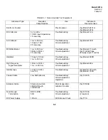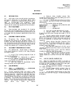
Model 5261A
Section V
Table 5-2
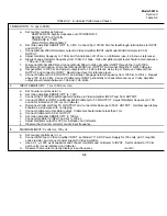
TABLE 5-2. In-Cabinet Performance Checks
1.BANDWIDTH: 10 cps to 50 Mc
a. Set counter controls as follows:
SAMPLE RATE slightly clockwise out of POWER OFF
SENSITIVITY to PLUG-IN
TIME BASE to .1 MS
FUNCTION to FREQUENCY
b. Set Video Amplifier SENSITIVITY to 3 MV. Connect (hp) 10100A 50-ohm feedthrough terminations to INPUT
and OUTPUT
c
Connect Model 200CD Oscillator output to Video Amplifier INPUT and Model 403B Voltmeter to 50
Ω
OUTPUT.
d. Adjust Oscillator frequency to 100 kc and for indication of 120 mv on Voltmeter (use -4 db line as reference).
e. Slowly change Oscillator frequency from 100kc to 10cps. Video Amplifier output level should remain between
- 7 db and -1 db limits.
f. Disconnect Model 200CD and connect Model 606A to Video Amplifier INPUT through the (hp)10100A
feedthrough termination. Disconnect Model 403B from OUTPUT and connect Model 411A RF Voltmeter.
g
Set generator to 1000 kc and adjust output level for -4 db reference as in step d. Remove Voltmeter from
OUTPUT and connect to INPUT. Record input level for reference level.
h. Connect Voltmeter to 50
Ω
OUTPUT and slowly change generator frequency from 1000 kc to 100 kc. Repeat
above 100 kc to 50 Mc. Connect Voltmeter to INPUT periodically to check reference level. Video Amplifier
output should remain between -7 db and -1 db limits.
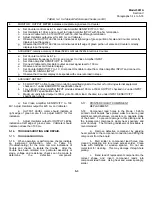
2.
INPUT SENSITIVITY. 1 mv to 300 mv rms.
a.
Set Counter controls as in 1 a.
b.
Set Video Amplifier SENSITIVITY to 1 MV
c.
Connect (hp) 10100A feedthrough terminations to Video Amplifier INPUT and 50
Ω
OUTPUT
d.
Connect 200CD to INPUT and Model 403B Voltmeter to 50
Ω
OUTPUT. Adjust Oscillator frequency to 100
kc and for indication of 100 mv on Voltmeter
e.
Disconnect Voltmeter from 50
Ω
OUTPUT and connect Oscilloscope to 50
Ω
OUTPUT. Oscilloscope display
should be a sine wave with no clipping.
f.
Connect Voltmeter to Oscillator output. Voltmeter should indicate less than 1 mv.
g
Connect Voltmeter to 50
Ω
OUTPUT.
h. Set Video Amplifier SENSITIVITY to 100 mv.
i. Connect Oscillator to INPUT and set to 100 kc.
j. Adjust Oscillator output for 300 mv indication on Voltmeter.
k. Observe that Counter correctly counts input frequency.
3.
MAXIMUM INPUT: 5 volts rms, 100 vdc
a. Set counter controls as in 1 a.
b. Connect BNC tee to Video Amplifier INPUT, set Model 711A DC Power Supply for 100 volts, add 1 megohm
series resistor, and connect power supply to Video Amplifier.
c
Use a 0.1
µ
f, 200 wvdc capacitor and connect Oscillator and Voltmeter to INPUT. Set Oscillator for 100 kc
and 5 volts rms as indicated on Voltmeter.
d.. Observe that counter correctly displays input frequency. (cont’d)
5-2
Summary of Contents for AM-4380/U 5261A
Page 2: ...A ...
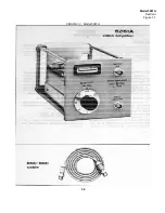
Page 7: ...Model 5261A Section I Figure 1 1 FIGURE 1 1 Model 5261A 1 0 ...
Page 19: ...Model 5261A Section V Figure 5 1 FIGURE 5 1 Schematic Diagram Notes 5 5 ...
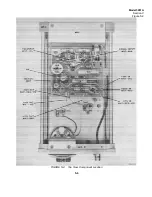
Page 20: ...Model 5261A Section V Figure 5 2 FIGURE 5 2 Top View Component Location 5 6 ...
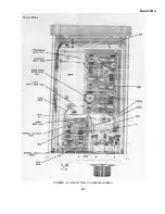
Page 21: ...Model 5261A FIGURE 5 3 Bottom View Component Location 5 7 ...
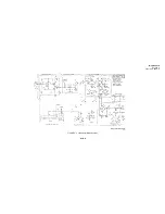
Page 22: ...Model 5261A Section V Figure 5 3 and 5 4 FIGURE 5 4 Video Amplifier Schematic 5 7 5 8 ...
Page 31: ...TM 11 6625 2906 14 P APPENIDIX C Additional Authorization List Not Applicable C 1 ...
Page 39: ...Model 5261A Appendix E FIGURE A 1 Top View Component Location E 3 ...
Page 40: ...Model 5261A Appendix E FIGURE A 2 Bottom View Component Location E 4 ...
Page 41: ...Model 5261A Appendix E FIGURE A 3 Video Amplifier Schematic E 5 ...
Page 42: ...Model 5261A Appendix E FIGURE A 4 A1 Preamplifier Component Location E 6 ...
Page 43: ...Model 5261A Appendix E FIGURE A 5 Video Amplifier Schematic E 7 ...
Page 44: ......
Page 45: ......
Page 47: ......
Page 48: ...PIN 046855 000 ...

