TM 11-6625-29061 L&?
D-3.
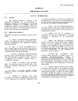
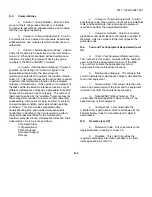
Column Entries
a.
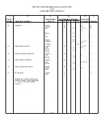
Column 1, Group Number.
Column 1 lists
group numbers, the purpose of which is to identify
components, assemblies, subassemblies, and modules
with the next higher assembly.
b. Column 2, Component/Assembly.
Column
2 contains the noun names of components, assemblies,
subassemblies, and modules for which maintenance is
authorized.
c
. Column 3, Maintenance Functions.
Column
3 lists the functions to be performed on the item listed in
column 2. When items are listed without maintenance
functions, it is solely for purpose of having the group
numbers in the MAC and RPSTL coincide.
d. Column 4, Maintenance Category.
Column 4
specifies, by the listing of a "worktime" figure in the
appropriate subcolumn(s), the lowest level of
maintenance authorized to perform the function listed in
column 3. This figure represents the active time required
to perform that maintenance function at the indicated
category of maintenance. If the number or complexity of
the tasks within the listed maintenance function vary at
different maintenance categories, appropriate "worktime"
figures will be shown for each category. The number of
task-hours specified by the "worktime" figure represents
the average time required to restore an item (assembly,
subassembly, component, module, end item or system)
to a serviceable condition under typical field operating
conditions. This time includes preparation time,
troubleshooting time, and quality assurance/quality
control time in addition to the time required to perform
the specific tasks identified for the maintenance
functions authorized in the maintenance allocation chart.
Subcolumns of column 4 are as follows:
C Operator/Crew
O Organizational
F Direct Support
H General Support
D Depot
e. Column 5, Tools and Equipment.
Column
specifies by code, those common tool sets (not individual
tools) and special tools, test, and support equipment
required to perform the designated function.
f.
Column 6, Remarks.
Column 6 contains
alphabetic code which leads to the remark in section IV,
Remarks, which is pertinent to the item opposite the
particular code.
D-4.
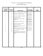
Tool and Test Equipment Requirement (sect
III)
a. Tool or Test Equipment Reference Code.
The numbers in this column coincide with the numbers
used in the tools and equipment column of the MAC.
The numbers indicate the applicable tool or test
equipment for the maintenance functions.
b.
Maintenance Category.
The codes in this
column indicate the maintenance category allocated the
tool or test equipment.
c. Nomenclature.
This column lists the noun
name and nomenclature of the tools and the equipment
required to perform the maintenance functions.
d. National/NATO Stock Number.
This
column lists the National/NATO stock number of the
specified tool or test equipment.
e. Tool Number.
This column lists the
manufacturer’s part number of the tool followed by the
Federal Supply Code for manufacturers (5-digit) in
parentheses.
D-5.
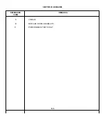
Remarks (sect IV)
a. Reference Code.
This code refers to the
appropriate item in section II, column 6.
b. Remarks.
This column provides the
required explanatory information necessary to clarify
items appearing in section II.
D-2
Summary of Contents for AM-4380/U 5261A
Page 2: ...A ...
Page 7: ...Model 5261A Section I Figure 1 1 FIGURE 1 1 Model 5261A 1 0 ...
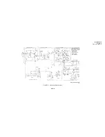
Page 19: ...Model 5261A Section V Figure 5 1 FIGURE 5 1 Schematic Diagram Notes 5 5 ...
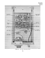
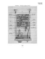
Page 20: ...Model 5261A Section V Figure 5 2 FIGURE 5 2 Top View Component Location 5 6 ...
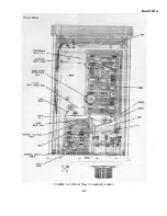
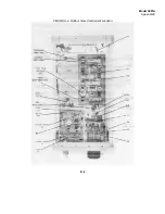
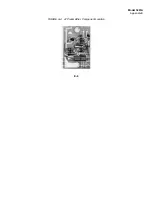
Page 21: ...Model 5261A FIGURE 5 3 Bottom View Component Location 5 7 ...
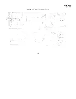
Page 22: ...Model 5261A Section V Figure 5 3 and 5 4 FIGURE 5 4 Video Amplifier Schematic 5 7 5 8 ...
Page 31: ...TM 11 6625 2906 14 P APPENIDIX C Additional Authorization List Not Applicable C 1 ...
Page 39: ...Model 5261A Appendix E FIGURE A 1 Top View Component Location E 3 ...
Page 40: ...Model 5261A Appendix E FIGURE A 2 Bottom View Component Location E 4 ...
Page 41: ...Model 5261A Appendix E FIGURE A 3 Video Amplifier Schematic E 5 ...
Page 42: ...Model 5261A Appendix E FIGURE A 4 A1 Preamplifier Component Location E 6 ...
Page 43: ...Model 5261A Appendix E FIGURE A 5 Video Amplifier Schematic E 7 ...
Page 44: ......
Page 45: ......
Page 47: ......
Page 48: ...PIN 046855 000 ...


