


Model 5261A
Section V
Table 5-1
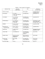
TABLE 5-1. Recommended Test Equipment
Instrument Type
Required
Use
Instrument
Characteristics
Recommended
Electronic Counter
Provide power
(hp) Model 5243L or
(hp) Model 5245L
DC Voltmeter
0 v to
±
25v;
Troubleshooting
(hp) Model 412A
10 M
Ω
input impedance;
1% accuracy
AC Voltmeter
1 mv to 500 mv;
Troubleshooting
(hp) Model 403B
10 cps to 1 Mc;
Circuit adjustment
2% accuracy
RF Millivoltmeter
1 mv to 500 mv;
Troubleshooting;
(hp) Model 411A with
500 kc to 50 Mc:
Circuit adjustment
(hp) 11025A Probe
3% accuracy
(formerly (hp) 411A-21E)
Oscillator
10 cps to 100 kc;
Troubleshooting;
(hp) Model 200CD
1 mv to 500 mv
Circuit adjustment
High Frequency
100 kc to 50 Mc:
Troubleshooting;
(hp) Model 606A
Signal Generator
1 mv- to 500 mv
Circuit adjustment
Oscilloscope
10 cps to 10 Mc;
Troubleshooting;
(hp) Model 175A with
5 mv/cm
(hp) Model 1752A
Coaxial Cable
Low Microphonics
Troubleshooting:;
(hp) 10507A
Circuit adjustment;
Operation
Extender Cable
50-pin connectors;
Permits operation
(hp) 10506B
straight-through
outside of counter
connections
Feed-through
BNC to BNC;
Troubleshooting:
(hp) 10100A
Termination
50
Ω
Circuit adjustment
(2 required)
DC Power Supply
100 vdc
Performance Check
(hp) 711A
5-0
Summary of Contents for AM-4380/U 5261A
Page 2: ...A ...
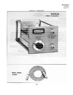
Page 7: ...Model 5261A Section I Figure 1 1 FIGURE 1 1 Model 5261A 1 0 ...
Page 19: ...Model 5261A Section V Figure 5 1 FIGURE 5 1 Schematic Diagram Notes 5 5 ...
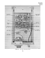
Page 20: ...Model 5261A Section V Figure 5 2 FIGURE 5 2 Top View Component Location 5 6 ...
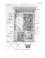
Page 21: ...Model 5261A FIGURE 5 3 Bottom View Component Location 5 7 ...
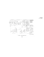
Page 22: ...Model 5261A Section V Figure 5 3 and 5 4 FIGURE 5 4 Video Amplifier Schematic 5 7 5 8 ...
Page 31: ...TM 11 6625 2906 14 P APPENIDIX C Additional Authorization List Not Applicable C 1 ...
Page 39: ...Model 5261A Appendix E FIGURE A 1 Top View Component Location E 3 ...
Page 40: ...Model 5261A Appendix E FIGURE A 2 Bottom View Component Location E 4 ...
Page 41: ...Model 5261A Appendix E FIGURE A 3 Video Amplifier Schematic E 5 ...
Page 42: ...Model 5261A Appendix E FIGURE A 4 A1 Preamplifier Component Location E 6 ...
Page 43: ...Model 5261A Appendix E FIGURE A 5 Video Amplifier Schematic E 7 ...
Page 44: ......
Page 45: ......
Page 47: ......
Page 48: ...PIN 046855 000 ...