


135
Appendix A. Installation and Maintenance
AC Line Power Supply Requirements
C AU T I O N
Please note that the power key on the front panel of the HP 8164A
Lightwave Measurement System does not stop the flow of power to the
instrument. The power key allows you to switch between stand-by mode
and power-on mode.
When the green power-on LED is lit, you can use the instrument. When
the orange stand-by mode LED is lit, the Lightwave Measurement
System is in stand-by mode. Do not remove the instrument covers - the
power supply is still operating in stand-by mode.
If you need to turn off the power, unplug the instrument at the mains or
remove the power cable connector from the appliance coupler at the
rear of the instrument. For this reason, the power cable connection
should be easily accessible - allowing you to turn off the power quickly.
If the instrument is in a cabinet, it must be disconnected from the line
power by the system’s line power switch.
The type of power cable shipped with each instrument depends on
the country of destination. Refer to Figure A-2 for the part numbers
of the power cables available.
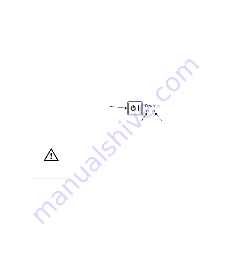
Figure A-1
Power Key
Power-on LED (green)
Stand-by mode LED (orange)
Power Key
Summary of Contents for 8163A Series
Page 1: ...HP 8163A Lightwave Multimeter HP 8164A Lightwave Measurement System User s Guide ...
Page 3: ...HP 8163A Lightwave Multimeter HP 8164A Lightwave Measurement System User s Guide ...
Page 13: ...13 Safety Summary ...
Page 25: ...1 1 Getting Started ...
Page 49: ...2 2 Additional Features ...
Page 61: ...3 3 Power Measurement ...
Page 76: ...76 Power Measurement How to Measure Power Figure 3 8 Manual Range Mode Within Range ...
Page 87: ...4 4 Laser Sources ...
Page 94: ...94 Using Laser Source Modules How to Use Laser Source Modules ...
Page 95: ...5 5 Tunable Lasers ...
Page 99: ...99 Tunable Laser Sources How to Set the Power Figure 5 1 Setting High Power parameters ...
Page 103: ...103 Tunable Laser Sources How to Set the Power Figure 5 3 Setting Attenuation ...
Page 130: ...130 Tunable Laser Sources How to Use Auxiliary Functions ...
Page 131: ...A A Installation and Maintenance ...
Page 159: ...B B Accessories ...
Page 167: ...C C Specifications ...
Page 175: ...D D Performance Tests ...
Page 188: ...188 Performance Tests Test Record ...
Page 192: ...192 Performance Tests Test Record ...
Page 193: ...E E Cleaning Procedures ...
Page 199: ...F F Firmware Updates ...
Page 204: ...204 F Firmware Updates Firmware Update Process ...


