3 How to Install Accessories In Your PC
Installing Accessory Boards
34
English
7
Secure the board by replacing the slot cover screw.
If you loosened the screws on adjacent slots, tighten them.
8
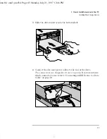
If you install a VESA-standard video adapter board which uses the
integrated video graphics controller, connect the accessory board’s
cable to the VESA pass-through connector on the system board. To
access the VESA pass-through connector, lift the power supply out
of its seating, and lay it upside down on the frame above the disk
drives. Remove the protection cover from the rear base of the PC.
NOTE
When the 1 MB video memory upgrade is installed on the integrated
video graphics controller, connecting a VESA-standard video adapter
board will disable this additional 1 MB of video memory and only the
first 1 MB of video memory will be used.
9
Install any other accessories before replacing the power supply and
the cover. Reconnect all cables and power cords.
10
If you used the VESA Pass-through connector, run the FCON.EXE
utility in HPUtils to enable the connection.
VESA pass-through connector for video boards
Protection cover
uno.bk : uno3_ins.fb4 Page 34 Monday, July 21, 1997 12:46 PM
Summary of Contents for 5/xx Series 4
Page 1: ...User s Guide HP Vectra VL 5 xx Series 4 uno bk 1bookf fb4 Page 1 Monday July 21 1997 12 46 PM ...
Page 3: ...User s Guide uno bk title fb4 Page iii Monday July 21 1997 12 46 PM ...
Page 6: ...vi Francais uno bk title fb4 Page vi Monday July 21 1997 12 46 PM ...
Page 132: ...120 Index uno bk uno ix Page 120 Monday July 21 1997 12 46 PM ...
Page 133: ...Regulatory Information and Warranty uno bk bckmttr fb4 Page 121 Monday July 21 1997 12 46 PM ...


