3478A
TM 11-6625-3071-14
Hybrid or the DC/Ohms Input Amplifier. Do the following:
a. Set the 3478A to the DC Volts Function and the
3V Range.
b. Make sure Autozero is turned off (see paragraph
7-A-8 step b).
c. If the reading on the 3478A is quiet with Autozero
off, the Input Hybrid is defective. Replace U102. If the
reading is still noisy, continue with the next step.
d. Connect pin 6 and pin 2 (U102 pin 3 and 9) of
U101 to each other.
e. Apply a 3V to the 3478A’s INPUT
Terminals.
f. Using a high impedance Digital Voltmeter (like
the 3456A) measure for a 3V at U101 pin 3.
g. If the voltage is noisy, replace the Input Hybrid
(U102).
h. If the voltage is stable, measure for a 3V
at pin 6 of U101.
i. If the voltage is noisy, replace U101. If the
voltage is stable, replace U102 (Input Hybrid).
7-A-31. DC CURRENT TROUBLESHOOTING
7-A-32. Make sure the DC Volts Function is operating
correctly on all ranges, before troubleshooting for dc
current failures. Go to paragraph 7-A-5 to troubleshoot
for DC Volts Failures. If the DC Volts Function is good,
the only components that can cause a current failure are
an open current fuse (F101), a defective resistor R107,
or the Input Hybrid U102. Make sure F101 and R107 are
good. If the resistor and fuse are good, U102 may be
defective. Before replacing U102, make sure the A/D
Controller (U462) is good. Go to paragraph 7-A-33 to
check the A/D Controller. If the controller is good,
replace U102.
7-A-33. CHECKING THE A/D CONTROLLER (U482)
7-A-34. Do the following to check the A/D Controller.
Refer to Schematic 3.
a. Turn the 3478A off.
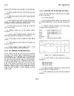
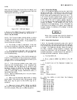
b. Move jumpers JM502, JM503, and JM403 to the
"D" position (JM403 pin 1 and 2), as shown in Figure 7-
A-1.
c. Obtain a Signature Analyzer. Set and connect
as follows (shown in Figure 7-A-1):
Start:
TP401 (JM403 pin 6) (
)
Stop:
TP402 (JM403 pin 5) (
)
Clock:
TP403 (JM403 pin 4) (
)
Hold:
Out
Self-Test:
Out
Gnd:
Ground Pin (next to C203)
Figure 7-A-1. JM403 SA Connection
d. Turn the 3478A on and check the following
signatures.
U462 pin 32: 7ACA
U462 pin 33: 20FO
U462 pin 34: 666H
e. If any signatures are wrong, go to Service Group
D (Flowchart D) for troubleshooting.
f. If the signatures are good, the Input Hybrid is
defective.
7-A-4
Summary of Contents for 3478A
Page 2: ...TM 11 6625 3071 14 A ...
Page 4: ...TM 11 6625 3071 14 C D BLANK ...
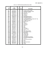
Page 12: ...TM 11 6625 3071 14 Table 1 1 Specification 1 2 ...
Page 13: ...TM 11 6625 3071 14 Table 1 1 Specifications Cont 1 3 ...
Page 14: ...TM 11 6625 3071 14 Table 1 1 Specifications Cont 1 4 ...
Page 53: ...TM 11 6625 3071 14 1 ...
Page 54: ...TM 11 6625 3071 14 2 ...
Page 55: ...TM 11 6625 3071 14 3 ...
Page 56: ...TM 11 6625 3071 14 4 ...
Page 87: ...TM 11 6625 3071 14 3478A Figure 7 D 3 Flowchart B 7 D 5 ...
Page 88: ...TM 11 6625 3071 14 3478A Figure 7 D 4 Flowchart C 7 D 6 ...
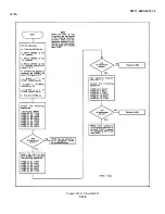
Page 91: ...TM 11 6625 3071 14 3478A Figure 7 D 6 Flowchart D 7 D 9 ...
Page 111: ...TM 11 6625 3071 14 Figure 7 F 17 3478A Simplified Reference Circuitry 7 F 16 ...
Page 122: ...TM 11 6625 3071 14 Table A 2 A 2 HP IB Worksheet A 4 ...
Page 137: ...TM 11 6625 3071 14 Figure 7 D 2 Flow chart A 7 D 3 ...
Page 139: ...TM 11 6625 3071 14 Figure 7 G 2 3478A Block Diagram 7 G 3 ...
Page 140: ...TM 11 6625 3071 14 Component Locator for Input Circuitry and Ohms Current Source 7 G 4 ...
Page 141: ...TM 11 6625 3071 14 Figure 7 G 3 Input Circuitry and Ohms Current Source 7 G 5 ...
Page 142: ...TM 11 6625 3071 14 F G 6 ...
Page 143: ...TM 11 6625 3071 14 2 Figure 7 G 4 AC to DC Converter 7 G 7 ...
Page 144: ...TM 11 6625 3071 14 Component Locator for A D Converter and Control Logic 7 G 8 ...
Page 145: ...TM 11 6625 3071 14 3 Figure 7 G 5 A D Converter and Control Logic 7 G 9 ...
Page 146: ...TM 11 6625 3071 14 7 G 10 ...
Page 147: ...TM 11 6625 3071 14 4 Figure 7 G 6 Power Supplies 7 G 11 7 G 12 blank ...
Page 148: ......
Page 149: ...PIN NO 057444 ...

