TM 11-6625-3071-14
3478A
feet are shaped to permit stacking with other half-
module Hewlett-Packard instruments.
2-16.
Rack Mounting
2-17.
The 3478A may be rack mounted by adding rack
mounting kit Option 908. The basic hardware and
instructions for rack mounting is contained in the kit. The
kit is designed to permit the 3478A to be mounted in a
standard 19 inch rack, provided that sufficient rear sup-
port is available.
2-18.
HP-IB INTERFACE CONNECTIONS
2-19.
The 3478A is compatible with the Hewlett-
Packard Interface Bus (HP-IB).
NOTE
HP-IB is Hewlett-Packard’s
implementation of IEEE Std. 488-1978,
"Standard Digital Interface For
Programmable Instrumentation" and
ANSI MC. 1.1.
2-20.
The interface connection is made by an HP-IB
Interface Cable to the 24 pin HP-IB connector located at
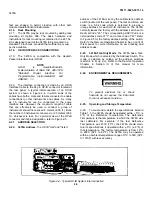
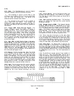
the rear panel. A typical interconnection of an HP-IB
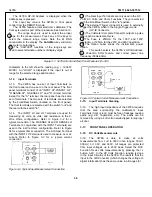
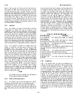
system is shown in Figure 2-4, in which ends of the
cables have both a male and female connector to enable
connections to other instruments and cables. As many
as 15 instruments can be connected to the same
interface bus. However, the maximum length of cable
that can effectively be used to connect a group of
instruments should not exceed 2 meters (6.56 ft.) times
the number of instruments connected, or 20 meters (65.6
ft.), whichever is less. For a pictorial view of the HP-IB
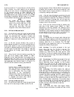
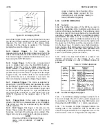
connector and its pin designation, refer to Figure 2-5.
2-21.
ADDRESS SELECTION
2-22.
3478A Address. The HP-IB "talk" and "listen"
address of the 3478A is set by the multimeter’s address
switch (located at the rear panel). The talk and listen ad-
dress is a 5-bit code which is selected to provide a
unique address for each HP-IB instrument. The 3478A
normally leaves the factory with the address switch set to
Decimal Code "23". The corresponding ASCII Code is a
listen address code of "7" and a talk code of "W". Refer
to Figure 2-5 for the factory address setting of the switch.
Refer to the Remote Operation Chapter in Sec- tion III of
this manual, for more information on ad- dressing and
address codes.
2-23.
3478A Talk-Only Mode. The 3478A has a Talk-
Only Mode which is selected by the Address Switch. The
mode is selected by setting all the address switches
(switch 4 to 8) up (on). Refer to the Remote Operation
Chapter in Section III of this manual for more
information.
2-24.
ENVIRONMENTAL REOUIREMENTS
To prevent electrical fire or shock
hazards, do not expose the instrument
to rain or excessive moisture.
2-25.
Operating and Storage Temperature
2-26.
To meet and maintain the specifications listed in
Table 1-1, the 3478A should be operated 5°C (±
9°F) of the Reference Temperature. The Reference
Temperature is the temperature in which the 3478A was
last calibrated. For example, if the last Reference
Temperature was 230C (73°F), the 3478A should main-
tain its specifications if operated within ± 5°C (± 9°F) of
that temperature. The factory temperature is from 18°C
to 280C (64°F to 82°F). The 3478A may be operated
within an ambient temperature range of 0°C to 55C (32°F
to 1310F) with less accuracy.
Figure 2-4. Typical HP-IB System Interconnection
2-3
Summary of Contents for 3478A
Page 2: ...TM 11 6625 3071 14 A ...
Page 4: ...TM 11 6625 3071 14 C D BLANK ...
Page 12: ...TM 11 6625 3071 14 Table 1 1 Specification 1 2 ...
Page 13: ...TM 11 6625 3071 14 Table 1 1 Specifications Cont 1 3 ...
Page 14: ...TM 11 6625 3071 14 Table 1 1 Specifications Cont 1 4 ...
Page 53: ...TM 11 6625 3071 14 1 ...
Page 54: ...TM 11 6625 3071 14 2 ...
Page 55: ...TM 11 6625 3071 14 3 ...
Page 56: ...TM 11 6625 3071 14 4 ...
Page 87: ...TM 11 6625 3071 14 3478A Figure 7 D 3 Flowchart B 7 D 5 ...
Page 88: ...TM 11 6625 3071 14 3478A Figure 7 D 4 Flowchart C 7 D 6 ...
Page 91: ...TM 11 6625 3071 14 3478A Figure 7 D 6 Flowchart D 7 D 9 ...
Page 111: ...TM 11 6625 3071 14 Figure 7 F 17 3478A Simplified Reference Circuitry 7 F 16 ...
Page 122: ...TM 11 6625 3071 14 Table A 2 A 2 HP IB Worksheet A 4 ...
Page 137: ...TM 11 6625 3071 14 Figure 7 D 2 Flow chart A 7 D 3 ...
Page 139: ...TM 11 6625 3071 14 Figure 7 G 2 3478A Block Diagram 7 G 3 ...
Page 140: ...TM 11 6625 3071 14 Component Locator for Input Circuitry and Ohms Current Source 7 G 4 ...
Page 141: ...TM 11 6625 3071 14 Figure 7 G 3 Input Circuitry and Ohms Current Source 7 G 5 ...
Page 142: ...TM 11 6625 3071 14 F G 6 ...
Page 143: ...TM 11 6625 3071 14 2 Figure 7 G 4 AC to DC Converter 7 G 7 ...
Page 144: ...TM 11 6625 3071 14 Component Locator for A D Converter and Control Logic 7 G 8 ...
Page 145: ...TM 11 6625 3071 14 3 Figure 7 G 5 A D Converter and Control Logic 7 G 9 ...
Page 146: ...TM 11 6625 3071 14 7 G 10 ...
Page 147: ...TM 11 6625 3071 14 4 Figure 7 G 6 Power Supplies 7 G 11 7 G 12 blank ...
Page 148: ......
Page 149: ...PIN NO 057444 ...


