background image

Memory module

Description

Spare part number

4-GB memory module (PC3, 12800, 1600-MHz)

641369-001

2-GB memory module (PC3, 12800, 1600-MHz)

652972-001

Before removing a memory module, follow these steps:

1.

Shut down the computer. If you are unsure whether the computer is off or in Hibernation, turn
the computer on, and then shut it down through the operating system.

2.

Disconnect all external devices connected to the computer.

3.

Disconnect the power from the computer by first unplugging the power cord from the AC outlet
and then unplugging the AC adapter from the computer.

4.

Remove the battery (see 

Battery on page 33

).

5.

Remove the service cover (see 

WLAN module on page 38

).

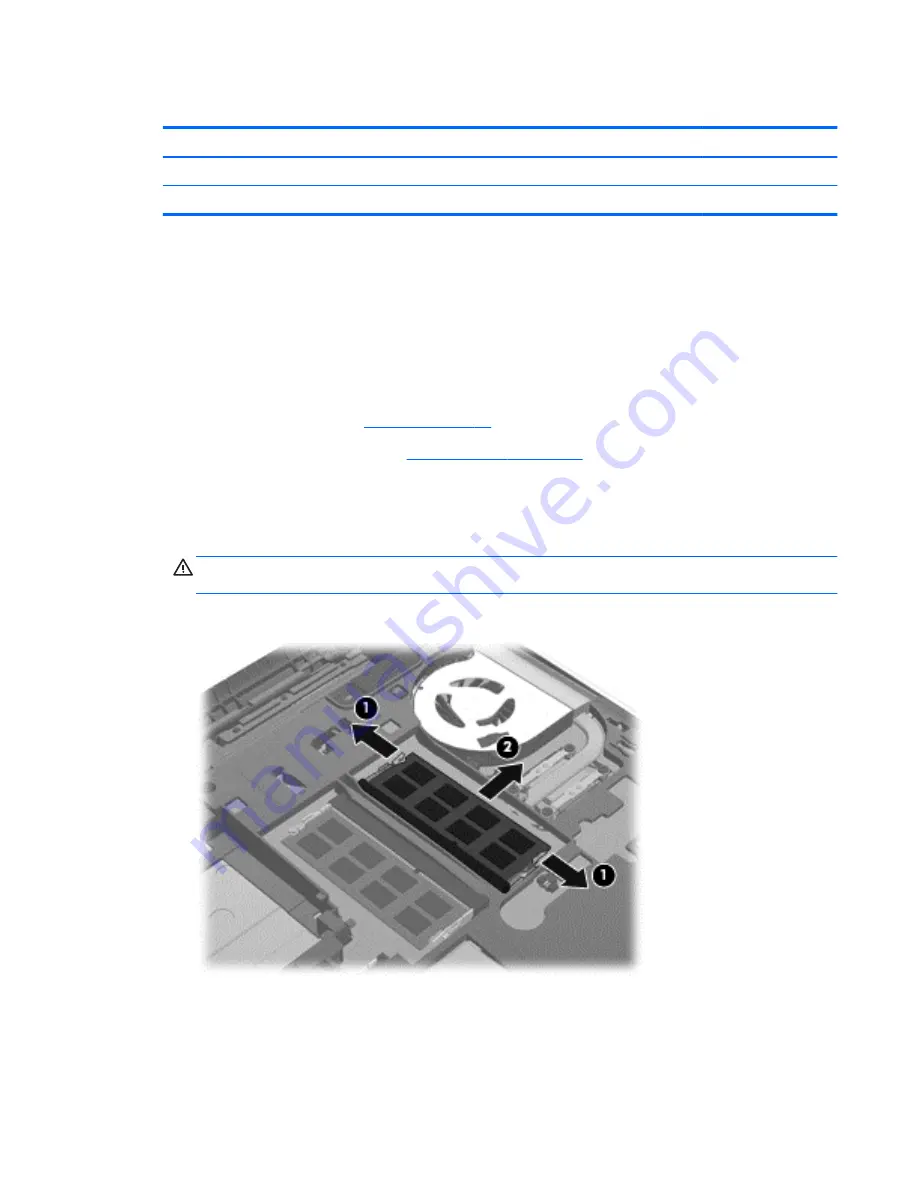
Remove the memory module:

1.

Spread the retaining tabs 

(1)

 on each side of the memory module slot to release the

memory module. (The memory module tilts up.)

CAUTION:

To prevent damage to the memory module, hold it by the edges only. Do not touch

the components on the memory module.

2.

Remove the memory module 

(2)

 by pulling it away from the slot at an angle.

Reverse this procedure to install a memory module.

Component replacement procedures

47

Summary of Contents for 3115m

Page 1: ...HP 3115m Notebook PC HP 3125 Notebook PC Maintenance and Service Guide ...

Page 2: ...proprietor The information contained herein is subject to change without notice The only warranties for HP products and services are set forth in the express warranty statements accompanying such products and services Nothing herein should be construed as constituting an additional warranty HP shall not be liable for technical or editorial errors or omissions contained herein Third Edition April 2...

Page 3: ...w another hard surface such as an adjoining optional printer or a soft surface such as pillows or rugs or clothing to block airflow Also do not allow the AC adapter to contact the skin or a soft surface such as pillows or rugs or clothing during operation The device and the AC adapter comply with the user accessible surface temperature limits defined by the International Standard for Safety of Inf...

Page 4: ...iv Safety warning notice ...

Page 5: ...rvice tag and PCID label 15 Service tag 15 PCID label 16 Computer major components 17 Display assembly subcomponents 20 Mass storage devices 22 Miscellaneous parts 23 Sequential part number listing 23 4 Removal and replacement procedures 26 Preliminary replacement requirements 26 Tools required 26 Service considerations 26 Plastic parts 26 Cables and connectors 26 Drive handling 27 Grounding guide...

Page 6: ...ink 66 5 Computer Setup BIOS and Advanced System Diagnostics in Windows 7 68 Using Computer Setup 68 Starting Computer Setup 68 Navigating and selecting in Computer Setup 68 Restoring factory settings in Computer Setup 69 Updating the BIOS 70 Determining the BIOS version 70 Downloading a BIOS update 70 Using Advanced System Diagnostics 71 6 Computer Setup BIOS and Advanced System Diagnostics in Wi...

Page 7: ...ls 83 Using f11 recovery tools 84 Using a Windows 7 operating system DVD purchased separately 85 9 Backup and recovery in Windows 8 86 Backing up your information 86 Performing a system recovery 87 Using the Windows recovery tools 87 Using f11 recovery tools 88 Using Windows 8 operating system media purchased separately 88 Using Windows Refresh for quick and easy recovery 89 Remove everything and ...

Page 8: ...viii ...

Page 9: ...r models equipped with an AMD E300 1 00 GHz processor AMD Radeon HD 7340 discrete class graphics on computer models equipped with an AMD E2 2000 processor AMD Radeon HD 7310 discrete class graphics on computer models equipped with an AMD E1 1500 processor Support for Blu ray playback with HD decode and DX11 support Panel 11 6 in high definition HD light emitting diode LED BrightView 1366 768 displ...

Page 10: ...ive External USB optical drive computer USB ports support 2A current SATA 12 7mm tray load Supports the following external optical drives Blu ray ROM DVD R RW Super Multi Double Layer Drive DVD RW and CD RW Super Multi Double Layer Combo Drive Audio and video Single digital microphone Beats Audio with Beats logo support Beats hotkey fn b Two integrated stereo speakers HP TrueVision high definition...

Page 11: ...g 1080p 1920 1080 60Hz RJ 45 Ethernet includes link and activity lights USB 2 0 3 ports VGA Dsub 15 pin supporting 2048 1536 external resolution 60 Hz hot plug and unplug and auto detection for correct output to wide aspect vs standard aspect video Keyboard pointing devices 97 Duracoat island style keyboard no spill resistance in charcoal and linen white finishes TouchPad with multi touch gestures...

Page 12: ...ndows 8 Multi language ML 64 bit Windows 8 Emerging Markets EM 64 bit FreeDos Serviceability End user replaceable parts AC adapter Battery Hard drive Memory modules SIM HP 3115m models only Solid state drive WLAN module WWAN module HP 3115m models only 4 Chapter 1 Product description ...

Page 13: ...if the display is closed while the power is on NOTE The display switch is not visible from the outside of the computer 2 WLAN antennas 2 Send and receive wireless signals to communicate with WLANs 3 WWAN antennas 2 select models only Send and receive wireless signals to communicate with WWANs 4 Internal microphone Records sound Display 5 ...

Page 14: ...ink YouCam from the list of apps 6 Webcam light On The webcam is in use The antennas are not visible from the outside of the computer For optimal transmission keep the areas immediately around the antennas free from obstructions To see wireless regulatory notices refer to the section of the Regulatory Safety and Environmental Notices that applies to your country or region These notices are located...

Page 15: ...Buttons Buttons 7 ...

Page 16: ...then select Power Options from the options displayed 2 QuickWeb button Windows 7 select models only Web browser button Windows 8 When the computer is off or in Hibernation press the button to open HP QuickWeb When the computer is in Microsoft Windows press the button to open the default Web browser When the computer is in HP QuickWeb press the button to open the Web browser QuickWeb allows you to ...

Page 17: ...e esc key 3 Windows logo key Windows 7 Displays the Windows Start menu Windows 8 Displays the Start screen NOTE Pressing the Windows logo key again will return you to the previous screen 4 Windows applications key Windows 7 Displays a shortcut menu for items beneath the cursor Windows 8 Displays options for a selected object 5 Action keys Execute frequently used system functions Keys 9 ...

Page 18: ...ation 2 Mute light Amber Computer sound is off Off Computer sound is on 3 Wireless light White An integrated wireless device such as a WLAN device and or a Bluetooth device is on Amber All wireless devices are off 4 Caps lock light On Caps lock is on 5 TouchPad light On The TouchPad is on Off The TouchPad is off 10 Chapter 2 External component identification ...

Page 19: ...ouble tap the TouchPad on off button to turn the TouchPad on and off 3 TouchPad zone Moves the pointer and selects or activates items on the screen 4 TouchPad left button Functions like the left button on an external mouse 5 TouchPad right button Functions like the right button on an external mouse Front Component Description Speakers 2 Produce sound TouchPad 11 ...

Page 20: ... mishandled or stolen 4 Vent Enables airflow to cool internal components NOTE The computer fan starts up automatically to cool internal components and prevent overheating It is normal for the internal fan to cycle on and off during routine operation 5 Hard drive light Blinking white The hard drive is being accessed Amber HP ProtectSmart Hard Drive Protection has temporarily parked the hard drive N...

Page 21: ...t the volume before putting on headphones earbuds or a headset For additional safety information refer to the Regulatory Safety and Environmental Notices NOTE When a device is connected to the jack the computer speakers are disabled 3 Audio in microphone jack Connects an optional computer headset microphone stereo array microphone or monaural microphone 4 USB 2 0 ports 2 Connect optional USB 2 0 d...

Page 22: ...the battery bay 4 Vent Enables airflow to cool internal components NOTE The computer fan starts up automatically to cool internal components and prevent overheating It is normal for the internal fan to cycle on and off during routine operation 5 Service cover Provides access to the hard drive bay a memory module slot the SIM slot select models only the WLAN module and the WWAN module select models...

Page 23: ... identifier that is unique to each product Part number Product number p n 3 This number provides specific information about the product s hardware components The part number helps a service technician to determine what components and parts are needed Warranty period 4 This number describes the duration in years of the warranty period for the computer Model description select models only 5 This is ...

Page 24: ...t the notebook firmware BIOS back to factory shipped specifications when replacing the system board The label may have a different number of characters depending on the operating system on the computer Windows 8 models Non Windows 8 models 16 Chapter 3 Illustrated parts catalog ...

Page 25: ...Computer major components Computer major components 17 ...

Page 26: ...50 processor and WWAN capability 659512 001 AMD E450 processor without WWAN capability 659511 001 AMD E300 processor and WWAN capability 659510 001 AMD E300 processor without WWAN capability 659509 001 For use in HP 3125 models AMD E2 2000 processor without WWAN capability and without Windows 8 702958 001 AMD E2 2000 processor without WWAN capability with Windows 8 Standard 702958 501 AMD E2 2000 ...

Page 27: ... isolators or screws These components are included in the Hard Drive Hardware Kit spare part number 664913 001 500 GB 5400 rpm SATA 7 0 mm 669299 001 320 GB 7200 rpm SATA 7 0 mm for use only in HP 3115m models 634862 002 320 GB 5400 rpm SATA 7 0 mm 645193 001 Solid state drive for use only in HP 3115m models 160 GB solid state drive 659933 001 128 GB solid state drive 675097 001 Hard Drive Hardwar...

Page 28: ... bezel includes display lid switch magnet For use in 3115m models 669025 001 For use in 3125 models 714296 001 2 Webcamera module 659516 001 Display Hinge Kit includes 659499 001 3a Left and right hinges 3b Left and right hinge brackets 20 Chapter 3 Illustrated parts catalog ...

Page 29: ...ables and transceivers and left and right WWAN antenna cables and transceivers 659492 001 7 Display enclosure in charcoal finish For use with computer models equipped with WLAN only capability includes WLAN antenna cables and transceivers 659493 001 For use with computer models equipped with WLAN and WWAN capability WLAN antenna cables and transceivers and WWAN antenna cables and transceivers 6716...

Page 30: ...0 rpm SATA 7 0 mm for use only in HP 3115m models 634862 002 320 GB 5400 rpm SATA 7 0 mm 645193 001 2 Solid state drive for use only in HP 3115m models 160 GB solid state drive 659933 001 128 GB solid state drive 675097 001 Hard Drive Hardware Kit includes 3a Hard drive bracket 3b Hard drive connector cable 3c Hard drive isolators Screws not illustrated 22 Chapter 3 Illustrated parts catalog ...

Page 31: ...y for use only with computer models without WWAN capability 626729 001 HP keyed cable lock 630813 001 Ralink 3592BC8 802 11a b g n 2 2 WiFi and Bluetooth 3 0 HS Combo Adapter for use in HP 3115m models 632155 001 HP hs2340 HSPA Mobile Broadband Module for use in HP 3115m models 634862 002 320 GB 7200 rpm hard drive only does not include bracket connector cable isolators or screws SATA 7 0 mm for u...

Page 32: ...thermal material 659511 001 System board for use only with computer models equipped with an AMD E450 processor but not WWAN capability includes processor and replacement thermal material 659512 001 System board for use only with computer models equipped with an AMD E450 processor and WWAN capability includes processor and replacement thermal material 659513 001 Top cover in charcoal finish include...

Page 33: ...models Latin America 699028 DB1 Keyboard in charcoal finish for use in HP 3125 models in Canada 702958 001 System board for use in HP 3125 models with an AMD E2 2000 processor without WWAN capability and without Windows 8 702958 501 System board for use in HP 3125 models with an AMD E2 2000 processor without WWAN capability and with Windows 8 Standard 702958 601 System board for use in HP 3125 mod...

Page 34: ...sembly can damage plastic parts Use care when handling the plastic parts Apply pressure only at the points designated in the maintenance instructions Cables and connectors CAUTION When servicing the computer be sure that cables are placed in their proper locations during the reassembly process Improper cable placement can damage the computer Cables must be handled with extreme care to avoid damage...

Page 35: ...ing guidelines Electrostatic discharge damage Electronic components are sensitive to electrostatic discharge ESD Circuitry design and structure determine the degree of sensitivity Networks built into many integrated circuits provide some protection but in many cases ESD contains enough power to alter device parameters or melt silicon junctions A discharge of static electricity from a finger or oth...

Page 36: ...floor 12 000 V 5 000 V 3 000 V Motions of bench worker 6 000 V 800 V 400 V Removing DIPS from plastic tube 2 000 V 700 V 400 V Removing DIPS from vinyl tray 11 500 V 4 000 V 2 000 V Removing DIPS from Styrofoam 14 500 V 5 000 V 3 500 V Removing bubble pack from PCB 26 500 V 20 000 V 7 000 V Packing PCBs in foam lined box 21 000 V 11 000 V 5 000 V 28 Chapter 4 Removal and replacement procedures ...

Page 37: ...nd and that proper materials are selected to avoid static charging When grounding is not possible use an ionizer to dissipate electric charges Workstation guidelines Follow these grounding workstation guidelines Cover the workstation with approved static shielding material Use a wrist strap connected to a properly grounded work surface and use properly grounded tools and equipment Use conductive f...

Page 38: ... between the operator and ground To be effective the conductive must be worn in contact with the skin The following grounding equipment is recommended to prevent electrostatic damage Antistatic tape Antistatic smocks aprons and sleeve protectors Conductive bins and other assembly or soldering aids Nonconductive foam Conductive tabletop workstations with ground cords of one megohm resistance Static...

Page 39: ...l number provided on the service tag The battery must be removed to access the service tag See Battery on page 33 for battery removal procedures Item Component Description 1 Product name This is the product name affixed to the front of the computer 2 Serial number s n This is an alphanumeric identifier that is unique to each product 3 Part number Product number p n This number provides specific in...

Page 40: ...dentifier used to locate documents drivers and support for the computer Computer feet The computer feet are adhesive backed rubber pads There are 2 oblong rubber feet that attach to the rear corner covers as indicated in the following illustration These feet are available in the Rubber Kit spare part number 664996 001 32 Chapter 4 Removal and replacement procedures ...

Page 41: ...computer by first unplugging the power cord from the AC outlet and then unplugging the AC adapter from the computer Remove the battery 1 Slide the battery service cover latch 1 to release the battery 2 Pivot the front edge of the battery 2 up and back 3 Remove the battery from the computer To insert the battery 1 Align the tabs on the rear edge of the battery with the notches on the rear edge of t...

Page 42: ...on and then shut it down through the operating system 2 Disconnect all external devices connected to the computer 3 Disconnect the power from the computer by first unplugging the power cord from the AC outlet and then unplugging the AC adapter from the computer 4 Remove the battery see Battery on page 33 Remove the SIM 1 Press in on the SIM 1 to release it from the SIM slot 2 Remove the SIM 2 from...

Page 43: ...ge 33 5 Remove the service cover see WLAN module on page 38 Remove the display panel 1 Turn the computer right side up with the front toward you 2 Open the computer 3 Flex the inside edges of the top edge 1 the left and right sides 2 and the bottom edge 3 of the display bezel until the bezel disengages from the display enclosure 4 Remove the display bezel 4 The display bezel includes the display h...

Page 44: ...ion turn the computer on and then shut it down through the operating system 2 Disconnect all external devices connected to the computer 3 Disconnect the power from the computer by first unplugging the power cord from the AC outlet and then unplugging the AC adapter from the computer 4 Remove the battery see Battery on page 33 5 Remove the display bezel see Display panel on page 35 6 Remove the dis...

Page 45: ...2 Disconnect the webcamera module cable 2 from the webcamera module 3 Remove the webcamera module Reverse this procedure to install the webcamera module Component replacement procedures 37 ...

Page 46: ... and then receive a warning message remove the module to restore device functionality and then contact technical support Before removing the WLAN module follow these steps 1 Shut down the computer If you are unsure whether the computer is off or in Hibernation turn the computer on and then shut it down through the operating system 2 Disconnect all external devices connected to the computer 3 Disco...

Page 47: ...ect the WLAN antenna cables 1 from the terminals on the WLAN module NOTE The 1 WLAN antenna cable is connected to the WLAN module 1 terminal The 2 WLAN antenna cable is connected to the WLAN module 2 terminal 5 Remove the Phillips PM2 0 3 7 screw 2 that secures the WLAN module to the system board The WLAN module tilts up Component replacement procedures 39 ...

Page 48: ...ent incorrect insertion into the memory module slot NOTE If the WLAN antennas are not connected to the terminals on the WLAN module the protective sleeves must be installed on the antenna connectors as shown in the following illustration Reverse this procedure to install the WLAN module 40 Chapter 4 Removal and replacement procedures ...

Page 49: ...er If you are unsure whether the computer is off or in Hibernation turn the computer on and then shut it down through the operating system 2 Disconnect all external devices connected to the computer 3 Disconnect the power from the computer by first unplugging the power cord from the AC outlet and then unplugging the AC adapter from the computer 4 Remove the battery see Battery on page 33 5 Remove ...

Page 50: ...ent incorrect insertion into the memory module slot NOTE If the WWAN antennas are not connected to the terminals on the WWAN module the protective sleeves must be installed on the antenna connectors as shown in the following illustration Reverse this procedure to install the WWAN module 42 Chapter 4 Removal and replacement procedures ...

Page 51: ...plugging the AC adapter from the computer 4 Remove the battery see Battery on page 33 5 Remove the service cover see WLAN module on page 38 Remove the RTC battery NOTE Steps 1 and 2 apply to computer models with WWAN capability See step 3 for RTC battery removal information on computer models without WLAN capability 1 Disconnect the RTC battery cable 1 from the system board 2 Remove the RTC batter...

Page 52: ...e RTC battery from the socket on the system board Reverse this procedure to install the RTC battery on computer models with WLAN capability When installing the RTC battery make sure the sign faces up 44 Chapter 4 Removal and replacement procedures ...

Page 53: ...ut down the computer If you are unsure whether the computer is off or in Hibernation turn the computer on and then shut it down through the operating system 2 Disconnect all external devices connected to the computer 3 Disconnect the power from the computer by first unplugging the power cord from the AC outlet and then unplugging the AC adapter from the computer 4 Remove the battery see Battery on...

Page 54: ...tor cable 1 the screws 2 the bracket 3 or the isolators 4 remove and replace the components The bracket connector cable isolators and screws are available in the Hard Drive Hardware Kit spare part number 664913 001 Reverse this procedure to reassemble and install the hard drive 46 Chapter 4 Removal and replacement procedures ...

Page 55: ... computer by first unplugging the power cord from the AC outlet and then unplugging the AC adapter from the computer 4 Remove the battery see Battery on page 33 5 Remove the service cover see WLAN module on page 38 Remove the memory module 1 Spread the retaining tabs 1 on each side of the memory module slot to release the memory module The memory module tilts up CAUTION To prevent damage to the me...

Page 56: ...urn the computer on and then shut it down through the operating system 2 Disconnect all external devices connected to the computer 3 Disconnect the power from the computer by first unplugging the power cord from the AC outlet and then unplugging the AC adapter from the computer 4 Remove the battery see Battery on page 33 5 Remove the service cover see WLAN module on page 38 Remove the keyboard 1 R...

Page 57: ...re included in the Rubber Kit spare part number 664996 001 4 Remove the three Phillips PM2 0 5 7 screws that secure the keyboard to the computer 5 Rest and secure the computer on its right side 6 Partially open the computer Component replacement procedures 49 ...

Page 58: ...e computer right side up with the front toward you 9 Lift the rear edge of the keyboard 1 and then swing the keyboard up and forward until it rests upside down on the palm rest 10 Release the zero insertion force ZIF connector 2 to which the keyboard cable is attached and then disconnect the keyboard cable 3 from the system board 50 Chapter 4 Removal and replacement procedures ...

Page 59: ...11 Remove the keyboard 3 Reverse this procedure to install the keyboard Component replacement procedures 51 ...

Page 60: ... cord from the AC outlet and then unplugging the AC adapter from the computer 4 Remove the battery see Battery on page 33 5 Remove the service cover see WLAN module on page 38 6 Remove the rear covers see Keyboard on page 48 Remove the display assembly subcomponents 1 Release the wireless antenna cables 1 from the clips 2 and routing channel built into the base enclosure 2 Disconnect the display p...

Page 61: ...zel display panel and webcamera module removal procedures 6 If it is necessary to replace the hinges a Remove the display assembly b Remove the display bezel c Remove the display panel d Remove the four Phillips PM2 0 4 2 1 screws that secure the hinges to the display enclosure Component replacement procedures 53 ...

Page 62: ...b Remove the display bezel c Remove the display panel d Remove the left display hinge e Release the webcamera cable 1 from the display enclosure The webcamera cable is attached to the display enclosure with double sided tape f Release the display panel cable from the clip 2 built into the display enclosure near the left display hinge area 54 Chapter 4 Removal and replacement procedures ...

Page 63: ...ips PM2 0 4 2 screw 1 that secures the right enclosure bracket to the display enclosure f Remove the left and right enclosure brackets 2 The left and right display enclosure brackets are included in the Display Hinge Kit spare part number 659499 001 g Release the wireless antenna cables 3 from the clips 4 and routing channels built into the display enclosure h Detach the WLAN transceivers 5 from t...

Page 64: ...t it down through the operating system 2 Disconnect all external devices connected to the computer 3 Disconnect the power from the computer by first unplugging the power cord from the AC outlet and then unplugging the AC adapter from the computer 4 Remove the battery see Battery on page 33 5 Remove the service cover see WLAN module on page 38 6 Remove the keyboard see Keyboard on page 48 7 Remove ...

Page 65: ...ven Phillips PM2 5 7 0 screws that secure the top cover to the computer 4 Turn the computer right side up with the front toward you 5 Open the computer 6 Disconnect the following cables from the system board 1 Power button board cable 2 TouchPad button board cable 3 Speaker cable Component replacement procedures 57 ...

Page 66: ...install the top cover Speakers Description Spare part number Speaker Kit includes left and right speakers and cable 659508 001 Before removing the speakers follow these steps 1 Shut down the computer If you are unsure whether the computer is off or in Hibernation turn the computer on and then shut it down through the operating system 2 Disconnect all external devices connected to the computer 58 C...

Page 67: ...see WLAN module on page 38 b Keyboard see Keyboard on page 48 c Top cover see Top cover on page 56 Remove the speakers 1 Turn the top cover upside down with the front edge toward you 2 Release the speaker cables from the clips built into the TouchPad 1 and top cover 2 3 Release the speakers from the clips 3 built into the top cover 4 Remove the speakers and cables 4 Reverse this procedure to insta...

Page 68: ... computer 4 Remove the battery see Battery on page 33 and then remove the following components a Service cover see WLAN module on page 38 b Keyboard see Keyboard on page 48 c Top cover see Top cover on page 56 Remove the TouchPad button board and cable 1 Turn the top cover upside down with the front edge toward you 2 Release the ZIF connector to which the TouchPad cable is attached and then discon...

Page 69: ...ese steps 1 Shut down the computer If you are unsure whether the computer is off or in Hibernation turn the computer on and then shut it down through the operating system 2 Disconnect all external devices connected to the computer 3 Disconnect the power from the computer by first unplugging the power cord from the AC outlet and then unplugging the AC adapter from the computer 4 Remove the battery ...

Page 70: ...an on page 64 Heat sink see Heat sink on page 66 Remove the system board 1 Lift the left side of the system board 1 until it rests at an angle 2 Remove the system board 2 by sliding it up and to the left at an angle Reverse this procedure to install the system board 62 Chapter 4 Removal and replacement procedures ...

Page 71: ...rom the AC outlet and then unplugging the AC adapter from the computer 4 Remove the battery see Battery on page 33 and then remove the following components a Service cover see WLAN module on page 38 b Keyboard see Keyboard on page 48 c Top cover see Top cover on page 56 d System board see System board on page 61 Remove the power connector cable 1 Turn the system board upside down with the right si...

Page 72: ...ut down the computer If you are unsure whether the computer is off or in Hibernation turn the computer on and then shut it down through the operating system 2 Disconnect all external devices connected to the computer 3 Disconnect the power from the computer by first unplugging the power cord from the AC outlet and then unplugging the AC adapter from the computer 4 Remove the battery see Battery on...

Page 73: ...4 Remove the fan 3 Reverse this procedure to install the fan Component replacement procedures 65 ...

Page 74: ...r on and then shut it down through the operating system 2 Disconnect all external devices connected to the computer 3 Disconnect the power from the computer by first unplugging the power cord from the AC outlet and then unplugging the AC adapter from the computer 4 Remove the battery see Battery on page 33 and then remove the following components a Service cover see WLAN module on page 38 b Keyboa...

Page 75: ...d with the heat sink and system board spare part kits The following illustration shows the replacement thermal material locations on a computer model equipped with an AMD processor and a graphics subsystem with discrete memory Thermal paste is used on the processor 1 and the heat sink section 2 that services it Reverse this procedure to install the heat sink Component replacement procedures 67 ...

Page 76: ... Startup Menu message is displayed at the bottom of the screen 2 Press f10 to enter Computer Setup Navigating and selecting in Computer Setup To navigate and select in Computer Setup follow these steps 1 Turn on or restart the computer and then press esc while the Press the ESC key for Startup Menu message is displayed at the bottom of the screen To select a menu or a menu item use the tab key and...

Page 77: ...ter Setup NOTE Restoring defaults will not change the hard drive mode To return all settings in Computer Setup to the values that were set at the factory follow these steps 1 Turn on or restart the computer and then press esc while the Press the ESC key for Startup Menu message is displayed at the bottom of the screen 2 Press f10 to enter Computer Setup 3 Use a pointing device or the arrow keys to...

Page 78: ...ly when the computer is connected to reliable external power using the AC adapter Do not download or install a BIOS update while the computer is running on battery power docked in an optional docking device or connected to an optional power source During the download and installation follow these instructions Do not disconnect power on the computer by unplugging the power cord from the AC outlet D...

Page 79: ...onents are functioning correctly System Tune Up runs longer and more comprehensive tests on memory modules hard drive SMART attributes the hard drive surface the battery and battery calibration video memory and the WLAN module status Start up test This test analyzes the main computer components that are required to start the computer Run in test This test repeats the start up test and checks for i...

Page 80: ...yed in the lower left corner of the screen press esc When the Startup Menu is displayed press f2 2 Click the diagnostic test you want to run and then follow the on screen instructions NOTE If you need to stop a diagnostics test while it is running press esc 72 Chapter 5 Computer Setup BIOS and Advanced System Diagnostics in Windows 7 ...

Page 81: ...e the Press the ESC key for Startup Menu message is displayed at the bottom of the screen 2 Press f10 to enter Computer Setup Navigating and selecting in Computer Setup To navigate and select in Computer Setup follow these steps 1 Turn on or restart the computer and then press esc while the Press the ESC key for Startup Menu message is displayed at the bottom of the screen To select a menu or a me...

Page 82: ...faults will not change the hard drive mode To return all settings in Computer Setup to the values that were set at the factory follow these steps 1 Turn on or restart the computer and then press esc while the Press the ESC key for Startup Menu message is displayed at the bottom of the screen 2 Press f10 to enter Computer Setup 3 Use a pointing device or the arrow keys to select File Restore Defaul...

Page 83: ...nd install a BIOS update only when the computer is connected to reliable external power using the AC adapter Do not download or install a BIOS update while the computer is running on battery power docked in an optional docking device or connected to an optional power source During the download and installation follow these instructions Do not disconnect power on the computer by unplugging the powe...

Page 84: ...g correctly System Tune Up runs longer and more comprehensive tests on memory modules hard drive SMART attributes the hard drive surface the battery and battery calibration video memory and the WLAN module status Start up test This test analyzes the main computer components that are required to start the computer Run in test This test repeats the start up test and checks for intermittent problems ...

Page 85: ...nu message is displayed in the lower left corner of the screen press esc When the Startup Menu is displayed press f2 2 Click the diagnostic test you want to run and then follow the on screen instructions NOTE If you need to stop a diagnostics test while it is running press esc Using Advanced System Diagnostics 77 ...

Page 86: ...rent 18 5 V dc 3 5 A 65 W Temperature Operating 5 C to 35 C 41 F to 95 F Nonoperating 20 C to 60 C 4 F to 140 F Relative humidity noncondensing Operating 10 to 90 Nonoperating 5 to 95 Maximum altitude unpressurized Operating 15 m to 3 048 m 50 ft to 10 000 ft Nonoperating 15 m to 12 192 m 50 ft to 40 000 ft NOTE Applicable product safety standards specify thermal limits for plastic surfaces The de...

Page 87: ...mber of colors Up to 16 8 million Contrast ratio 200 1 typical Brightness 200 nits typical Pixel resolution Pitch 0 197 mm 0 197 mm Format 1366 768 Configuration RGB vertical stripe Backlight LED Character display 80 25 Total power consumption 2 0 W Viewing angle 65 horizontal 50 vertical typical 11 6 inch display specifications 79 ...

Page 88: ...y ATA security Seek times typical read including setting Single track 1 5 ms 1 5 ms 1 5 ms 1 5 ms Average read write 12 13 ms 11 13 ms 11 13 ms 11 13 ms Maximum 24 ms 22 ms 22 ms 22 ms Logical blocks 1 250 263 728 976 773 168 628 142 448 488 397 168 Disk rotational speed 5400 rpm 7200 and 5400 rpm 7200 and 5400 rpm 5400 rpm Operating temperature 0 C to 60 C 32 F to 140 F 1 GB 1 billion bytes when ...

Page 89: ...drive Backing up your information Creating a system image select models only Scheduling automatic backups select models only Creating system restore points Recovering individual files Restoring the computer to a previous state Recovering information using recovery tools NOTE For detailed instructions perform a search for these topics in Help and Support In case of system instability HP recommends ...

Page 90: ...lick the Burn button to start the burning process Backing up your information Recovery after a system failure is as good as your most recent backup Immediately after software setup you should create system repair discs select models only using HP Recovery Disc Creator using the installed optical drive select models only or an optional external optical drive and back up your system As you add new s...

Page 91: ... and Restore to recover information you have previously backed up You can also use Windows Startup Repair to fix problems that might prevent Windows from starting correctly f11 recovery tools You can use the f11 recovery tools to recover your original hard drive image The image includes the Windows operating system and software programs installed at the factory NOTE If you are unable to boot start...

Page 92: ...air 5 Follow the on screen instructions NOTE For additional information on recovering information using the Windows tools perform a search for these topics in Help and Support Using f11 recovery tools CAUTION Using f11 recovery tools completely erases hard drive contents and reformats the hard drive All files you have created and any software installed on the computer are permanently removed The f...

Page 93: ...ed When reformatting is complete the recovery process helps you restore the operating system as well as drivers software and utilities To initiate recovery using a Windows 7 operating system DVD NOTE This process takes several minutes 1 If possible back up all personal files 2 Restart the computer and then insert the Windows 7 operating system DVD into the optical drive before the Windows operatin...

Page 94: ...acking up your information Recovery after a system failure is as good as your most recent backup You should create system repair media and your initial backup immediately after initial system setup As you add new software and data files you should continue to back up your system on a regular basis to maintain a reasonably current backup As you add new software and data files you should continue to...

Page 95: ... computer and you cannot use the system repair media you previously created select models only you must purchase Windows 8 operating system media to reboot the computer and repair the operating system Using the Windows recovery tools To recover information you previously backed up From the Start screen type help and then select Help and Support To recover your information using Automatic Repair fo...

Page 96: ...e Windows 8 operating system media and the Driver Recovery media both purchased separately 3 If the HP Recovery partition is listed restart the computer and then press esc while the Press the ESC key for Startup Menu message is displayed at the bottom of the screen 4 Press f11 while the Press F11 for recovery message is displayed on the screen 5 Follow the on screen instructions Using Windows 8 op...

Page 97: ...assword when using Refresh See Help and Support for more information From the Start screen type help and then select Help and Support To start Refresh 1 On the Start screen point to the far right upper or lower corner of the screen to display the charms 2 Click Settings 3 Click Change PC settings in the bottom right corner of the screen and then select General from the PC settings screen 4 Under R...

Page 98: ... Change PC settings in the bottom right corner of the screen and then select General from the PC settings screen 4 Under Remove everything and reinstall Windows select Get started and follow the on screen instructions Using HP Software Setup HP Software Setup can be used to reinstall drivers or select software that has been corrupted or deleted from the system 1 From the Start screen type HP Softw...

Page 99: ...ng requirements are applicable to all countries and regions The length of the power cord set must be at least 1 5 m 5 0 ft and no more than 2 0 m 6 5 ft All power cord sets must be approved by an acceptable accredited agency responsible for evaluation in the country or region where the power cord set will be used The power cord sets must have a minimum current capacity of 10 A and a nominal voltag...

Page 100: ... Denmark DEMKO 1 Finland FIMKO 1 France UTE 1 Germany VDE 1 India ISI 1 Israel SII 1 Italy IMQ 1 Japan JIS 3 The Netherlands KEMA 1 New Zealand SANZ 1 Norway NEMKO 1 The People s Republic of China CCC 4 Saudi Arabia SASO 7 Singapore PSB 1 South Africa SABS 1 South Korea KTL 5 Sweden SEMKO 1 Switzerland SEV 1 Taiwan BSMI 6 Thailand TISI 1 The United Kingdom ASTA 1 92 Chapter 10 Power cord set requi...

Page 101: ...mm or 1 25 mm conductor size The wall plug must be a two pole grounding type with a Japanese Industrial Standard C8303 7 A 125 V ac configuration 4 The flexible cord must be Type RVV 3 conductor 0 75 mm conductor size Power cord set fittings appliance coupler and wall plug must bear the CCC certification mark 5 The flexible cord must be Type H05VV F 3X0 75 mm conductor size KTL logo and individual...

Page 102: ...in general household waste Follow the local laws and regulations in your area for battery disposal HP encourages customers to recycle used electronic hardware HP original print cartridges and rechargeable batteries For more information about recycling programs see the HP Web site at http www hp com recycle 94 Chapter 11 Recycling ...

Page 103: ...2 spare part number 32 computer major components 17 computer part number 31 Computer Setup navigating and selecting 68 73 restoring factory settings 69 74 computer specifications 78 connectors service considerations 26 D Digital Media Slot 13 display components 5 specifications 79 display assembly removal 52 subcomponents 20 display bezel removal 35 spare part number 20 24 35 Display Cable Kit spa...

Page 104: ...0 11 webcam 6 wireless 10 lock spare part numbers 23 M mass storage device precautions 27 removal 45 spare part numbers 22 45 memory module product description 1 removal 47 spare part numbers 19 23 47 microphone location 5 product description 2 microphone jack 13 model description 32 model name 1 monitor port 13 mouse spare part number 23 mute light 10 N network jack 13 O operating system product ...

Page 105: ...emoval 58 spare part number 18 24 58 specifications computer 78 display 79 hard drive 80 system board removal 61 spare part numbers 18 24 61 system repair disc 81 system restore points 81 T tools required 26 top cover removal 56 spare part number 18 24 56 TouchPad button 11 TouchPad button board removal 60 spare part number 18 24 60 TouchPad components 11 TouchPad light 10 11 12 TouchPad on off bu...

Reviews: