background image

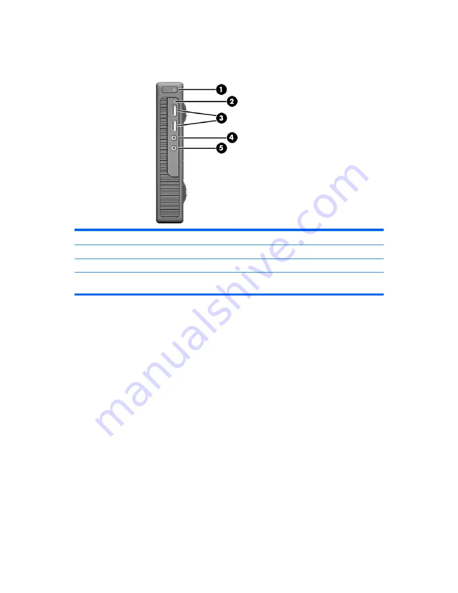
Front panel components

Drive configuration may vary by model.

1

Dual-State Power Button

4

Microphone Connector

2

Hard Drive Activity Light

5

Headphone Connector

3

USB 3.0 Ports


NOTE:

The Power On Light is normally white when the power is on. If it is flashing red, there is a problem with the

computer and it is displaying a diagnostic code. Refer to the 

Maintenance and Service Guide

 to interpret the code.

2

Chapter 1   Product features

Summary of Contents for 260 G1

Page 1: ...Maintenance and Service Guide HP 260 G1 Desktop Mini PC ...

Page 2: ...ions contained herein This document contains proprietary information that is protected by copyright No part of this document may be photocopied reproduced or translated to another language without the prior written consent of Hewlett Packard Company First Edition February 2015 Document Part Number 790975 001 Product notice This guide describes features that are common to most models Some features ...

Page 3: ...w another hard surface such as an adjoining optional printer or a soft surface such as pillows or rugs or clothing to block airflow Also do not allow the AC adapter to contact the skin or a soft surface such as pillows or rugs or clothing during operation The device and the AC adapter comply with the user accessible surface temperature limits defined by the International Standard for Safety of Inf...

Page 4: ...iv Safety warning notice ...

Page 5: ...tic 10 Preventing electrostatic damage to equipment 11 Personal grounding methods and equipment 11 Grounding the work area 11 Recommended materials and equipment 12 Operating guidelines 12 Routine care 13 General cleaning safety precautions 13 Cleaning the Computer Case 13 Cleaning the keyboard 13 Cleaning the monitor 14 Cleaning the mouse 14 Service considerations 14 Tools and software requiremen...

Page 6: ... board callouts 42 WLAN antennas 43 Changing from desktop to tower configuration 46 5 Computer Setup F10 Utility 47 Computer Setup F10 Utilities 47 Using Computer Setup F10 Utilities 48 Computer Setup File 49 Computer Setup Storage 50 Computer Setup Security 51 Computer Setup Power 53 Computer Setup Advanced 53 Recovering the Configuration Settings 54 6 Troubleshooting without diagnostics 55 Safet...

Page 7: ...s 90 Why run HP PC Hardware Diagnostics 90 How to access and run HP PC Hardware Diagnostics 90 Downloading HP PC Hardware Diagnostics UEFI to a USB device 91 10 System backup and recovery 92 Backing up restoring and recovering in Windows 8 1 or Windows 8 92 Creating recovery media and backups 92 Restoring and recovering using Windows tools 92 Using Reset when the system is not responding 93 Recove...

Page 8: ...very media select models only 99 Using HP Recovery Disc operating system discs select models only 100 Appendix A Power Cord Set Requirements 102 General Requirements 102 Japanese Power Cord Requirements 102 Country Specific Requirements 103 Appendix B Statement of Volatility 104 Appendix C Specifications 106 Index 107 viii ...

Page 9: ...or a complete listing of the hardware and software installed in the computer run the diagnostic utility included on some computer models only NOTE This computer model can be used in a tower orientation or a desktop orientation The tower stand is sold separately Standard configuration features 1 ...

Page 10: ...rd Drive Activity Light 5 Headphone Connector 3 USB 3 0 Ports NOTE The Power On Light is normally white when the power is on If it is flashing red there is a problem with the computer and it is displaying a diagnostic code Refer to the Maintenance and Service Guide to interpret the code 2 Chapter 1 Product features ...

Page 11: ...nnector for powered audio devices green 2 DisplayPort Monitor Connector 7 USB 2 0 Ports black with keyboard wakeup function 3 RJ 45 network Jack 8 USB 3 0 Ports blue 4 Power Cord Retainer Clip 9 Cable lock slot 5 VGA Monitor Connector blue Rear panel components 3 ...

Page 12: ...ach computer has a unique serial number and a product ID number that are located on the exterior of the computer Keep these numbers available for use when contacting customer service for assistance 4 Chapter 1 Product features ...

Page 13: ... computer go to http partsurfer hp com select your country or region and then follow the on screen instructions Computer major components Item Description 1 Access panel 2 Base enclosure 3 System board with embedded processor includes replacement thermal material Intel Core i5 4210U processor Without Windows operating system Windows 8 1 Standard Chassis spare parts 5 ...

Page 14: ...s 8 1 Standard Windows 8 1 Professional NetClone Intel Pentium 3558U processor Without Windows operating system Windows 8 1 Standard Windows 8 1 Professional NetClone Intel Celeron 2957U processor Without Windows operating system Windows 8 1 Standard Windows 8 1 Professional NetClone 6 Chapter 2 Illustrated parts catalog ...

Page 15: ...ription 1 Hard drive 500 GB 7200 rpm hard drive 2 5 inch 2 Solid state drives 256 GB self encrypting SED OPAL 2 0 128 GB 3 M 2 solid state drive 32 GB M 2 2242DS Grommet hard drive not illustrated Chassis spare parts 7 ...

Page 16: ...ard drive connector and cable 5 Hard drive cage 6 Antennas and transceivers 7 WLAN module Realtek RTL8188EE 802 11b g n Wireless LAN Driver Rubber screw covers Power supply 65W 89 efficiency Memory modules SODIMM PC3 12800 8 Chapter 2 Illustrated parts catalog ...

Page 17: ...ion 8 GB 4 GB 2 GB Stand HP Ultraslim Keyed Cable Lock Grommet hard drive Adapters DisplayPort to HDMI 1 4 DisplayPort to VGA DisplayPort to DVI DisplayPort cable Mouse USB optical Keyboard USB Chassis spare parts 9 ...

Page 18: ...ally for a while but it has been degraded in the internal layers reducing its life expectancy Networks built into many integrated circuits provide some protection but in many cases the discharge contains enough power to alter device parameters or melt silicon junctions Generating static The following table shows that Different activities generate different amounts of static electricity Static elec...

Page 19: ...e connected and fit snugly into the banana plug connector on the grounding mat or workstation Heel straps Toe straps Boot straps can be used at standing workstations and are compatible with most types of shoes or boots On conductive floors or dissipative floor mats use them on both feet with a maximum of one megohm 10 resistance between the operator and ground Static Shielding Protection Levels Me...

Page 20: ...r on a sturdy level surface Leave a 10 2 cm 4 inch clearance on all vented sides of the computer and above the monitor to permit the required airflow Never restrict the airflow into the computer by blocking any vents or air intakes Do not place the keyboard with the keyboard feet down directly against the front of the desktop unit as this also restricts airflow Occasionally clean the air vents on ...

Page 21: ... a mild dishwashing liquid diluted with water Rinse well by wiping it with a cloth or swab dampened with clear water For stubborn stains use isopropyl rubbing alcohol No rinsing is needed as the alcohol will evaporate quickly and not leave a residue After cleaning always wipe the unit with a clean lint free cloth Occasionally clean the air vents on the computer Lint and other foreign matter can bl...

Page 22: ...e housing Pull out any debris from the ball socket and wipe the ball with a clean dry cloth before reassembly To clean the mouse body follow the procedures in Cleaning the Computer Case on page 13 Service considerations Listed below are some of the considerations that you should keep in mind during the disassembly and assembly of the computer Tools and software requirements To service the computer...

Page 23: ...e ensure that you are discharged of static electricity While handling a drive avoid touching the connector Do not use excessive force when inserting a drive Avoid exposing a hard drive to liquids temperature extremes or products that have magnetic fields such as monitors or speakers Lithium coin cell battery The battery that comes with the computer provides power to the real time clock and has a m...

Page 24: ...ology SMART ATA drives for the HP Personal Computers have built in drive failure prediction that warns the user or network administrator of an impending failure or crash of the hard drive The SMART drive tracks fault prediction and failure indication parameters such as reallocated sector count spin retry count and calibration retry count If the drive determines that a failure is imminent it genera...

Page 25: ...on page 10 for initial safety procedures 1 Remove disengage any security devices that prohibit opening the computer 2 Remove all removable media such as a USB flash drive from the computer 3 Turn off the computer properly through the operating system then turn off any external devices CAUTION Turn off the computer before disconnecting any cables Regardless of the power on state voltage is always p...

Page 26: ...o the front of the computer 1 3 Remove the screws from the two holes closest to the front of the computer 2 4 Turn the computer over 5 Loosen the screw on the rear of the computer 1 then slide the panel forward and lift if off the computer 2 To install the access panel reverse the removal procedure 18 Chapter 4 Removal and replacement procedures ...

Page 27: ...up the data from the old hard drive so that you can transfer the data to the new hard drive 1 Prepare the computer for disassembly Preparation for disassembly on page 17 2 Remove the access panel Access panel on page 18 3 Push down the release lever next to the rear of the hard drive 1 Hold the release lever down and slide the drive back until it stops then lift the drive up and out of the bay 2 H...

Page 28: ...ata cable from the hard drive 5 Transfer the silver and blue isolation mounting guide screws from the old hard drive to the new hard drive Reverse this procedure to replace the hard drive 20 Chapter 4 Removal and replacement procedures ...

Page 29: ... up to 16 GB of memory DDR3L SDRAM SODIMMs For proper system operation the SODIMMs must be industry standard 204 pin unbuffered non ECC PC3 12800 DDR3L 1333 MHz compliant 1 35 volt DDR3L SDRAM SODIMMs The DDR3L SDRAM SODIMMs must also support CAS latency 11 DDR3L 1333 MHz 11 11 11 timing contain the mandatory Joint Electronic Device Engineering Council JEDEC specification In addition the computer ...

Page 30: ...populated in one channel only The system will operate in a higher performing dual channel mode if the memory capacity of the SODIMM in Channel A is equal to the memory capacity of the SODIMM in Channel B The system will operate in flex mode if the memory capacity of the SODIMM in Channel A is not equal to the memory capacity of the SODIMM in Channel B In flex mode the channel populated with the le...

Page 31: ... use memory modules with gold plated metal contacts to prevent corrosion and or oxidation resulting from having incompatible metals in contact with each other Static electricity can damage the electronic components of the computer or optional cards Before beginning these procedures ensure that you are discharged of static electricity by briefly touching a grounded metal object When handling a memo...

Page 32: ...the socket 2 5 Slide the new SODIMM into the socket at approximately a 30 angle 1 then press the SODIMM down 2 so that the latches lock it in place NOTE A memory module can be installed in only one way Match the notch on the module with the tab on the memory socket 24 Chapter 4 Removal and replacement procedures ...

Page 33: ...6 Align the memory door over the SODIMMs lower the door and then press the door into place The computer automatically recognizes the additional memory when you turn on the computer Memory 25 ...

Page 34: ...atic electricity can damage the electronic components of the computer or optional equipment Before beginning these procedures ensure that you are discharged of static electricity by briefly touching a grounded metal object NOTE The lifetime of the lithium battery can be extended by plugging the computer into a live AC wall socket The lithium battery is only used when the computer is NOT connected ...

Page 35: ...battery in place and lift the battery out of the holder 2 b Pull back on the clip 1 and slide the replacement battery down into the holder 2 CAUTION Be sure the symbol on the battery is facing the outer edge of the computer Replacing the battery 27 ...

Page 36: ... for disassembly Preparation for disassembly on page 17 2 Remove the access panel Access panel on page 18 3 From the inside of the computer disconnect the speaker cable from the system board connector 1 4 Disconnect the WLAN antenna cable that is secured to the speaker from the WLAN module connector 2 The antenna that is secured to the speaker routes to the connector labeled 1 on the WLAN module 2...

Page 37: ...gage it from the system board To install the speaker reverse the removal procedures When installing the speaker insert the clips on the bottom of the speaker into the slots in the system board NOTE The following image shows an upside down view of the computer and speaker Speaker 29 ...

Page 38: ... on page 17 2 Remove the access panel Access panel on page 18 3 Disconnect the fan cable from the system board connector labeled CPUFAN 1 4 Remove the two Torx screws that secure the fan to the heat sink 2 5 Remove the fan from the heat sink 3 To install the fan reverse the removal procedure 30 Chapter 4 Removal and replacement procedures ...

Page 39: ... Remove the fan Fan on page 30 4 In the order indicated on the heat sink loosen the four captive Torx screws 1 4 and then lift the heat sink out of the computer 5 CAUTION Be sure the loosen the screws in the order indicated by the numbers stamped on the heat sink CAUTION To reduce a degradation in thermal performance be sure not to touch the thermal grease on the surface of the processor or the he...

Page 40: ...ccess the drive cable connector underneath and then disconnect the cable Then you can slide the cable out of the drive cage 1 Prepare the computer for disassembly Preparation for disassembly on page 17 2 Remove the access panel Access panel on page 18 3 Remove the hard drive Hard drive on page 19 4 Remove the four Torx screws 1 that secure the drive cage to the computer 32 Chapter 4 Removal and re...

Page 41: ...drive cage 2 Lift the drive cage up to access the drive cable connector under the drive cage CAUTION To avoid damage to the drive cable or connector be careful not to inadvertently disconnect the cable when lifting the drive cage Drive cage and drive cable 33 ...

Page 42: ...SATA1 connector on the system board Lift the drive cage and drive cable from the computer 7 Slide the drive cable out of the slot in the drive cage To install the drive cage and drive cable reverse the removal procedures 34 Chapter 4 Removal and replacement procedures ...

Page 43: ...ts to a transceiver on the side of the chassis NOTE WLAN module appearance may vary 1 Prepare the computer for disassembly Preparation for disassembly on page 17 2 Remove the access panel Access panel on page 18 3 Remove the hard drive Hard drive on page 19 4 Remove the drive cage Drive cage and drive cable on page 32 5 Disconnect the antenna cables from the module 1 6 Remove the screws 2 that sec...

Page 44: ...ule away from the socket to remove 3 To install the WLAN module reverse the removal procedure NOTE WLAN modules are designed with a notch to prevent incorrect insertion 36 Chapter 4 Removal and replacement procedures ...

Page 45: ...ge To remove the M 2 SSD 1 Prepare the computer for disassembly Preparation for disassembly on page 17 2 Remove the access panel Access panel on page 18 3 Remove the hard drive Hard drive on page 19 4 Remove the drive cage Drive cage and drive cable on page 32 5 Remove the Phillips screw that secures the module to the computer M 2 solid state drive 37 ...

Page 46: ...ee angle and then pull it away to remove it from the socket To install the M 2 SSD reverse the removal procedures NOTE M 2 SSDs are designed with a notch to prevent incorrect insertion 38 Chapter 4 Removal and replacement procedures ...

Page 47: ...ing system Windows 8 1 Standard Windows 8 1 Professional NetClone System board with embedded Intel Celeron 2957U processor Without Windows operating system Windows 8 1 Standard Windows 8 1 Professional NetClone 1 Prepare the computer for disassembly Preparation for disassembly on page 17 2 Remove the access panel Access panel on page 18 3 Remove the memory modules Memory on page 21 4 Remove the ha...

Page 48: ... Information When replacing the system board you must reprogram the SMBIOS information on the affected computer Failure to reprogram the board will result in eventual failure such as an activation failure need to reactivate the system or a system recovery failure To update SMBIOS information in Computer Setup 1 Turn on or restart the computer 2 Press Esc while the Press the ESC key for Startup Men...

Page 49: ...the SKU or Product Number including Localization Code Support Asset Tag Enter the 18 byte identifier assigned to the computer Support Feature Byte Enter the Feature Byte string The feature byte string is case sensitive The label includes spaces after every four characters You can enter or ignore these spaces their only purpose is to help with data entry There is a character limitation of 40 bytes ...

Page 50: ...nnector DIMM2 Black Secondary memory socket X1PCIEXP11 Black WLAN module socket CMOS Yellow CMOS reset button M 2 Black Solid state drive socket DIMM1 Black Primary memory socket PSWD Black blue Password header and jumper BAT Black RTC battery SATA1 Black Hard drive data connector 42 Chapter 4 Removal and replacement procedures ...

Page 51: ...re the computer for disassembly Preparation for disassembly on page 17 2 Remove the access panel Access panel on page 18 3 Remove the speaker Speaker on page 28 4 Remove the hard drive Hard drive on page 19 5 Remove the drive cage Drive cage and drive cable on page 32 6 Remove the fan Fan on page 30 7 Remove the heat sink Heat sink on page 31 8 Disconnect the remaining antenna cable from the WLAN ...

Page 52: ... removed speaker assembly The transceiver is secured to the speaker using adhesive 11 Pull the antenna cable through the hole in the speaker assembly and then separate the antenna from the speaker assembly 44 Chapter 4 Removal and replacement procedures ...

Page 53: ...ve the auxiliary transceiver from the inside of the chassis The transceiver is secured to the chassis using adhesive Reverse the removal procedure to install the WLAN antennas and transceivers WLAN antennas 45 ...

Page 54: ...e is always present on the system board as long as the system is plugged into an active AC outlet You must disconnect the power cord to avoid damage to the internal components of the computer 5 Orient the computer so that its right side is facing up and place the computer in the optional stand NOTE To stabilize the computer in a tower orientation HP recommends the use of the optional tower stand 6...

Page 55: ...d regardless of the mode selected To manually switch to Post Messages Enabled during POST press any key except F1 through F12 Establish an Ownership Tag the text of which is displayed each time the system is turned on or restarted Enter the Asset Tag or property identification number assigned by the company to this computer Enable the power on password prompt during system restarts warm boots as w...

Page 56: ...yed or Follow the Windows 8 1 instructions for rebooting the computer into the Computer Setup F10 Utility 3 A choice of five headings appears in the Computer Setup Utilities menu File Storage Security Power and Advanced 4 Use the arrow left and right keys to select the appropriate heading Use the arrow up and down keys to select the option you want then press Enter To return to the Computer Setup ...

Page 57: ...t Displays copyright notice Set Time and Date Allows you to set system time and date Default Setup Save Current Settings as Default Saves the current system configuration settings as the default Restore Factory Settings as Default Restores the factory system configuration settings as the default Apply Defaults and Exit Applies the currently selected default settings and clears any established pass...

Page 58: ...h legacy boot sources such as a network interface card internal hard drive USB optical drive or internal optical drive are checked for a bootable operating system image Each device on the list may be individually excluded from or included for consideration as a bootable operating system source Specify the order of attached hard drives The first hard drive in the order will have priority in the boo...

Page 59: ... longer be used If you lose or forget the password the system board must be replaced This scenario is not covered under warranty To prevent the computer from becoming permanently unusable record your configured setup password or power on password in a safe place away from your computer Without these passwords the computer cannot be unlocked Setup Browse Mode appears if a setup password is set allo...

Page 60: ...sable Allows you to make sure an operating system is legitimate before booting to it making Windows resistant to malicious modification from preboot to full OS booting preventing firmware attacks UEFI and Windows Secure Boot only allow code signed by pre approved digital certificates to run during the firmware and OS boot process Default is disabled except for Windows 8 1 systems which have this s...

Page 61: ...essages enable disable Enabling this feature will cause the system to display POST error messages which are error messages displayed on the monitor during the Power On Self Test if the BIOS encounters some kind of problem while starting the PC A POST error message will only display on screen if the computer is capable of booting this far If the POST detects an error before this point a beep code i...

Page 62: ...wnload a corporate image to a hard drive The NIC option ROM takes up memory space below 1MB commonly referred to as DOS Compatibility Hole DCH space This space is limited This F10 option will allow users to disable the downloading of this embedded NIC option ROM thus giving more DCH space for additional PCI cards which may need option ROM space The default is enabled Recovering the Configuration S...

Page 63: ...ll help you diagnose the problem Refer to Appendix A POST error messages on page 80 for more information If the screen is blank plug the monitor into a different video port on the computer if one is available Or replace the monitor with a monitor that you know is functioning properly If you are working on a network plug another computer with a different cable into the network connection There may ...

Page 64: ...ing red The flashing lights are error codes that will help you diagnose the problem Refer to Appendix A POST error messages on page 80 for more information Turn up the brightness and contrast controls of the monitor if the monitor is dim Press and hold any key If the system beeps then the keyboard should be operating correctly Check all cable connections for loose connections or incorrect connecti...

Page 65: ... computer Before turning on the computer press and hold F10 Turn on the computer and continue to hold F10 until the Computer Setup F10 Utility is displayed or Follow the Windows 8 1 instructions for rebooting the computer into the Computer Setup F10 Utility Computer appears locked up and will not turn off when the power button is pressed Cause Solution Software control of the power switch is not f...

Page 66: ...use Solution System volume may be set low or muted 1 Check the Computer Setup settings to make sure the internal system speaker is not muted this setting does not affect the external speakers 2 Make sure the external speakers are properly connected and powered on and that the speakers volume control is set correctly 3 Use the system volume control available in the operating system to make sure the...

Page 67: ... not want to launch automatically and the click OK Some software applications especially games are stressful on the graphics subsystem 1 Lower the display resolution for the current application or consult the documentation that came with the application for suggestions on how to improve performance by adjusting parameters in the application 2 Add more memory 3 Upgrade the graphics solution Cause u...

Page 68: ...t of applications In the left column expand Computer right click on a drive select Properties and then select the Tools tab Under Error checking click Check Drive not found identified Cause Solution Cable could be loose Check cable connections The system may not have automatically recognized a newly installed device See reconfiguration directions in the Solving Hardware Installation Problems on pa...

Page 69: ...r the Hard Drive entry Computer will not boot from hard drive Cause Solution The device is attached to a SATA port that has been hidden in Computer Setup 1 Check SATA cable connections 2 Run the Computer Setup utility and ensure Device Available is selected for the device s SATA port in Security Device Security Boot order is not correct Run the Computer Setup utility and change boot sequence in St...

Page 70: ...will lose any unsaved data Monitor cable is plugged into the wrong connector Systems may have a monitor connection on both the motherboard or an add in card Try moving the monitor connection to a different connector on the back of the computer Monitor settings in the computer are not compatible with the monitor 1 In Control Panel select Category from the View by list then under Appearance and Pers...

Page 71: ...lure prior to video Replace the system board Monitor does not function properly when used with energy saver features Cause Solution Monitor without energy saver capabilities is being used with energy saver features enabled Disable monitor energy saver feature Dim characters Cause Solution The brightness and contrast controls are not set properly Adjust the monitor brightness and contrast controls ...

Page 72: ...at the computer power is off while connecting the video cable Out of Range displays on screen Cause Solution Video resolution and refresh rate are set higher than what the monitor supports Restart the computer and enter Safe Mode Change the settings to a supported setting then restart the computer so that the new settings take effect To enter Safe Mode in Windows 7 1 Restart the computer 2 Press a...

Page 73: ...t connection only Cause Solution Flat panel monitor s internal digital conversion circuits may be unable to correctly interpret the output synchronization of the graphics card 1 Select the monitor s Auto Adjustment option in the monitor s on screen display menu 2 Manually synchronize the Clock and Clock Phase on screen display functions To download a SoftPaq that will assist you with the synchroni...

Page 74: ...ut is the green receptacle Headphones or devices connected to the line out connector mute the internal speaker Turn on and use headphones or external speakers if connected or disconnect headphones or external speakers Computer is in Sleep state Press the power button to resume from Sleep state CAUTION When attempting to resume from Sleep state do not hold down the power button for more than four s...

Page 75: ...an speakers Some graphics cards support audio over the DisplayPort connection if applicable so multiple audio devices may be listed in Device Manager Make sure the correct device is being used To access Device Manager in Windows 7 click Start select Control Panel and then select Device Manager To access Device Manager in Windows 8 1 from the Start screen type c select Control Panel from the list o...

Page 76: ...pen box and then click OK If you are on a network you may not have made the connection to the printer Make the proper network connections to the printer Printer may have failed Run printer self test Printer will not turn on Cause Solution The cables may not be connected properly Reconnect all cables and check the power cord and electrical outlet Printer prints garbled information Cause Solution Th...

Page 77: ...ds Shut down your computer using the mouse and then restart the computer Keyboard needs repairs See the Worldwide Limited Warranty for terms and conditions Computer is in Sleep state Press the power button to resume from Sleep state CAUTION When attempting to resume from Sleep date do not hold down the power button for more than four seconds Otherwise the computer will shut down and you will lose ...

Page 78: ...t is jerky Cause Solution Mouse roller ball or the rotating encoder shafts that make contact with the ball are dirty Remove roller ball cover from the bottom of the mouse and clean the internal components with a mouse cleaning kit available from most computer stores Solving Hardware Installation Problems You may need to reconfigure the computer when you add or remove hardware such as an additional...

Page 79: ...t select Control Panel and then select Device Manager To access Device Manager in Windows 8 1 from the Start screen type c select Control Panel from the list of applications and then select Device Manager USB ports on the computer are disabled in Computer Setup Run the Computer Setup utility and ensure that Device available is selected for appropriate USB ports under Security USB Security Computer...

Page 80: ...n in Computer Setup Select Power Hardware Power Management S5 Maximum Power Savings S5 Wake on LAN is disabled some models Enable the S5 Wake on LAN option in Computer Setup Select Advanced Device Options S5 Wake on LAN Wake on LAN is not enabled To enable Wake on LAN in Windows 7 1 Select Start Control Panel Network and Sharing Center 2 Under Tasks select Manage network connections 3 Click Local ...

Page 81: ...ad and the Network Connections applet within Windows for link status To access Device Manager in Windows 7 click Start select Control Panel and then select Device Manager To access Device Manager in Windows 8 1 from the Start screen type c select Control Panel from the list of applications and then select Device Manager Network controller is disabled 1 Run Computer Setup and enable network control...

Page 82: ...ontrol Panel and configure the network controller To access Control Panel in Windows 7 click Start and then select Control Panel To access Control Panel in Windows 8 1 from the Start screen type c and then select Control Panel Network controller stopped working when an expansion board was added to the computer Cause Solution Network controller interrupt is shared with an expansion board Under the ...

Page 83: ... the computer will not boot the operating system NOTE The memory count will be affected by configurations with the Management Engine ME enabled The ME uses 8MB of system memory in single channel mode or 16MB of memory in dual channel mode to download decompress and execute the ME firmware for Out of Band OOB third party data storage and other management functions System will not boot or does not f...

Page 84: ...Memory is installed incorrectly or is bad 1 Reseat DIMMs Power on the system 2 Replace DIMMs one at a time to isolate the faulty module 3 Replace third party memory with HP memory 4 Replace the system board Solving USB flash drive problems If you encounter USB flash drive problems common causes and solutions are listed in the following table USB flash drive is not seen as a drive letter in Windows...

Page 85: ...ISP Cable DSL modem is not plugged in Plug in cable DSL modem You should see a power LED light on the front of the cable DSL modem Cable DSL service is not available or has been interrupted due to bad weather Try connecting to the Internet at a later time or contact your ISP If the cable DSL service is connected the cable LED light on the front of the cable DSL modem will be on The CAT5 UTP cable ...

Page 86: ... the applicable solutions listed in the following table Computer will not continue and the HP logo does not display Cause Solution ROM issue POST error has occurred Observe the beeps and LED lights on the front of the computer See Appendix A POST error messages on page 80 to determine possible causes See the Worldwide Limited Warranty for terms and conditions Computer will not continue after HP lo...

Page 87: ...oot select Advanced options and then select Automatic Repair Windows starts Automatic Repair 4 Select the account to use to begin Automatic Repair and type the password for the account Windows diagnoses the computer and attempts the repair it Illegal Operation has Occurred error message is displayed Cause Solution Software being used is not Microsoft certified for your version of Windows Verify th...

Page 88: ...ry x Days mode using Computer Setup NOTE For more information on Computer Setup see Computer Setup F10 Utility on page 47 POST numeric codes and text messages This section covers those POST errors that have numeric codes associated with them The section also includes some text messages that may be encountered during POST NOTE The computer will beep once after a POST text message is displayed on th...

Page 89: ...only memory 4 Verify proper memory module type 201 Memory Error RAM failure 1 Ensure memory modules are correctly installed 2 Verify proper memory module type 3 Remove and replace the identified faulty memory module s 4 If the error persists after replacing memory modules replace the system board 213 Incompatible Memory Module in Memory Socket s X X A memory module in memory socket identified in t...

Page 90: ...d if minimal graphics degrading is an issue 1720 SMART Hard Drive Detects Imminent Failure Hard drive is about to fail Some hard drives have a hard drive firmware patch that will fix an erroneous error message 1 Determine if hard drive is giving correct error message Run the Drive Protection System test under using F2 Diagnostics when booting the computer 2 Apply hard drive firmware patch if appli...

Page 91: ...ard 2220 USB Key Provisioning file has mismatch version Provisioning file contained on the USB key is not a valid version for the current ME firmware 1 Reboot the computer 2 If the error persists and system BIOS has been recently updated restore previous system BIOS version Otherwise update the ME firmware version 3 If the error still persists replace the system board Invalid Electronic Serial Num...

Page 92: ...ed A fan may be blocked or not turning OR The heat sink fan assembly is not properly attached to the processor 1 Ensure that the computer air vents are not blocked and the cooling fan is running 2 Open hood press power button and see if the fan spins If the processor fan is not spinning make sure the fan s cable is plugged onto the system board header 3 If fan is plugged in but is not spinning the...

Page 93: ...sh the system ROM with the latest BIOS image 2 Replace the system board Red Power LED flashes nine times once every second followed by a two second pause Beeps stop after fifth iteration but LEDs continue until problem is solved 9 System powers on but is unable to boot 1 Unplug the AC power cord from the computer wait 30 seconds then plug the power cord back in to the computer 2 Replace the system...

Page 94: ...mputer by resetting the password jumper CAUTION Pushing the CMOS button will reset CMOS values to factory defaults It is important to back up the computer CMOS settings before resetting them in case they are needed later Back up is easily done through Computer Setup See Computer Setup F10 Utility on page 47 for information on backing up the CMOS settings Resetting the password jumper CAUTION If yo...

Page 95: ...eader and jumper labeled PSWD NOTE For assistance locating the password jumper and other system board components see the system board components image at System board callouts on page 42 5 Remove the jumper from pins 1 and 2 6 Place the jumper on either pin 1 or 2 but not both so that it does not get lost 7 Replace the access panel and reconnect the external equipment 8 Plug in the computer and tu...

Page 96: ...shown current password 4 Press Enter Clearing and resetting the CMOS The computer s configuration memory CMOS stores information about the computer s configuration The CMOS button resets CMOS but does not clear the power on and setup passwords 1 Turn off the computer and any external devices and disconnect the power cord from the power outlet 2 Disconnect the keyboard monitor and any other externa...

Page 97: ...tlet The CMOS button will not clear CMOS if the power cord is connected NOTE For assistance locating the CMOS button and other system board components see the system board components image at System board callouts on page 42 5 Replace the access panel 6 Reconnect the external devices 7 Plug in the computer and turn on power NOTE You will receive POST error messages after clearing CMOS and rebootin...

Page 98: ...ected that requires hardware replacement a 24 digit Failure ID is generated This ID can then be provided to the call agent who will either schedule support or provide replacement parts How to access and run HP PC Hardware Diagnostics You can run the diagnostics from one of three places depending on your preference and the health of the computer 1 Turn on the computer and press Esc repeatedly until...

Page 99: ...k and then select Run Option 2 Support and Drivers pages Provides downloads for a specific product for earlier and later versions 1 Go to http www hp com 2 Point to Support located at the top of the page and then click Download Drivers 3 In the text box enter the product name and then click Go or Click Find Now to let HP automatically detect your product 4 Select your computer model and then selec...

Page 100: ...been replaced You will use a USB flash drive to create a bootable recovery drive that can be used to troubleshoot a computer that is unable to start The USB flash drive can be used to reinstall the original operating system and the programs that were installed at the factory NOTE Any information on the USB flash drive will be erased before the recovery media is created To create the Windows 8 1 re...

Page 101: ...nd the Driver Recovery media purchased separately see Recovery using Windows operating system media purchased separately on page 94 3 If the HP Recovery partition is listed restart the computer and then press esc while the HP logo is displayed The computer Startup Menu displays 4 Press f11 to select the System Recovery option 5 Choose your keyboard layout 6 Select Troubleshoot 7 Select Reset 8 Fol...

Page 102: ...yboard key 4 Follow the on screen instructions After the repair is completed and the Windows desktop appears 1 Remove the Windows operating system media and then insert the Driver Recovery media 2 Install the Hardware Enabling Drivers first and then install Recommended Applications Backing up restoring and recovering in Windows 7 Your computer includes tools provided by HP and Windows to help you ...

Page 103: ... computer create recovery media The media can be used to reinstall the original operating system in cases where the hard drive is corrupted or has been replaced There are two types of recovery media To determine which steps to follow for your computer 1 Click the Start button 2 Click All Programs If Security and Protection is listed continue with the steps in Creating recovery media using HP Recov...

Page 104: ... enough storage capacity it will appear grayed out and you must replace it with a larger USB flash drive Click Next 6 Follow the on screen instructions When the process is complete label the USB flash drive and store it in a secure place Creating recovery discs with HP Recovery Disc Creator select models only HP Recovery Disc Creator is a software program that offers an alternative way to create r...

Page 105: ...t are stored in their associated directories Save customized settings that appear in a window toolbar or menu bar by taking a screen shot of your settings The screen shot can be a time saver if you have to reset your preferences When backing up to discs number each disc after removing it from the drive NOTE For detailed instructions on various backup and restore options perform a search for these ...

Page 106: ... drive The recovery image is a file that contains a copy of the original factory shipped software To perform a System Recovery from a recovery image see System Recovery when Windows is responding on page 98 or System Recovery when Windows is not responding on page 99 Recovery media Run System Recovery from recovery media that you have created from files stored on your hard disk drive or purchased ...

Page 107: ...ions to continue 6 When Windows has loaded shut down the computer reconnect all peripheral devices and then turn the computer back on System Recovery using recovery media select models only Use the steps provided in this section if you created recovery media using Creating recovery media using HP Recovery Manager select models only on page 95 If you used HP Recovery Disc Creator to create a Window...

Page 108: ...stem DVD to reboot the computer and repair the operating system To order a Windows 7 operating system DVD contact support Go to http www hp com support select your country or region and follow the on screen instructions CAUTION Using a Windows 7 operating system DVD completely erases the hard drive contents and reformats the hard drive All files that you have created and any software that you have...

Page 109: ...ndows 7 operating system DVD and then insert the Driver Recovery DVD 2 Follow the on screen instructions to install the Hardware Enabling Drivers first and then install Recommended Applications Backing up restoring and recovering in Windows 7 101 ...

Page 110: ...cy responsible for evaluation in the country where the power cord set will be installed 2 The power cord set must have a minimum current capacity of 10A 7A Japan only and a nominal voltage rating of 125 or 250 volts AC as required by each country s power system 3 The diameter of the wire must be a minimum of 0 75 mm2 or 18AWG and the length of the cord must be between 1 8 m 6 feet and 3 6 m 12 fee...

Page 111: ... set fittings appliance coupler and wall plug must bear the certification mark of the agency responsible for evaluation in the country where it will be used 2 The flexible cord must be Type SVT or equivalent No 18 AWG 3 conductor The wall plug must be a two pole grounding type with a NEMA 5 15P 15A 125V or NEMA 6 15P 15A 250V configuration 3 Appliance coupler flexible cord and wall plug must bear ...

Page 112: ...s to flash the BIOS that are found on the website Flashing the BIOS will reset it back to factory settings 3 Turn on the system and while system is powering on and after the HP splash screen press the F10 key to enter BIOS setup screen 4 Select Security System Security from the main menu If the Embedded Security Device Support option is set to Disable skip to step 7 5 To erase all security keys fr...

Page 113: ...d and AC power cord and turn the computer on The passwords are now cleared and all other user configurable non volatile memory settings are reset to their factory default values 14 Enter the F10 setup utility 15 Select File Default Setup Restore Factory Settings as Default This will set the default settings back to the factory defaults 16 Select File Apply Defaults and Exit 17 Shut down the comput...

Page 114: ...he type and number of options installed Relative Humidity noncondensing Operating 15 80 15 80 Maximum Altitude unpressurized Operating Non operating 15 000 ft 15 000 ft 4572 m 4572 m Power Supply Rated Voltage Range1 Rated Line Frequency 100 240 VAC 50 60 Hz Maximum Operating Power 65W Idle Operating Power 30W 1 This system utilizes an active power factor corrected power supply This allows the sys...

Page 115: ...17 drive cage removal and replacement 32 Driver Recovery DVD creating 96 using for restore 100 Driver Recovery media Windows 94 Driver Recovery media Windows 8 1 94 E electrostatic discharge ESD 10 preventing damage 11 error codes 80 84 messages 80 F F10 Setup access problem 57 f11 recovery Windows 8 1 92 fan illustrated 8 removal and replacement 30 flash drive problems 76 flashing LEDs 84 front p...

Page 116: ...ting system media 94 removal and replacement battery 26 drive cage 32 fan 30 front bezel 18 hard drive 19 heat sink 31 memory 23 solid state drive 37 speaker 28 system board 39 WLAN antennas 43 WLAN module 35 removing battery 26 hard drive 19 resetting CMOS 86 password jumper 86 restoring the hard drive Windows 8 1 92 S safety and comfort 55 safety precautions cleaning 13 SATA connectors on system...

Page 117: ...7 Windows 7 operating system discs using for restore 100 Windows 7 operating system DVD creating 96 using for restore 100 Windows 7 operating system media creating 96 Windows 8 backup and restore 92 Windows 8 1 backup and restore 92 Driver Recovery media 94 f11 recovery 92 hard drive recovery 92 operating system DVD 94 recovery partition 92 restoring the hard drive 92 WLAN antennas removal and rep...

Reviews: