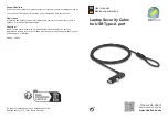
To remove the hard drive:
1.
Loosen the hard drive cover screw
(1)
, and then lift up
(2)
and remove the cover
(3)
. The hard
drive compartment cover is available in the Plastics Kit. For more information about the Plastics Kit,
see
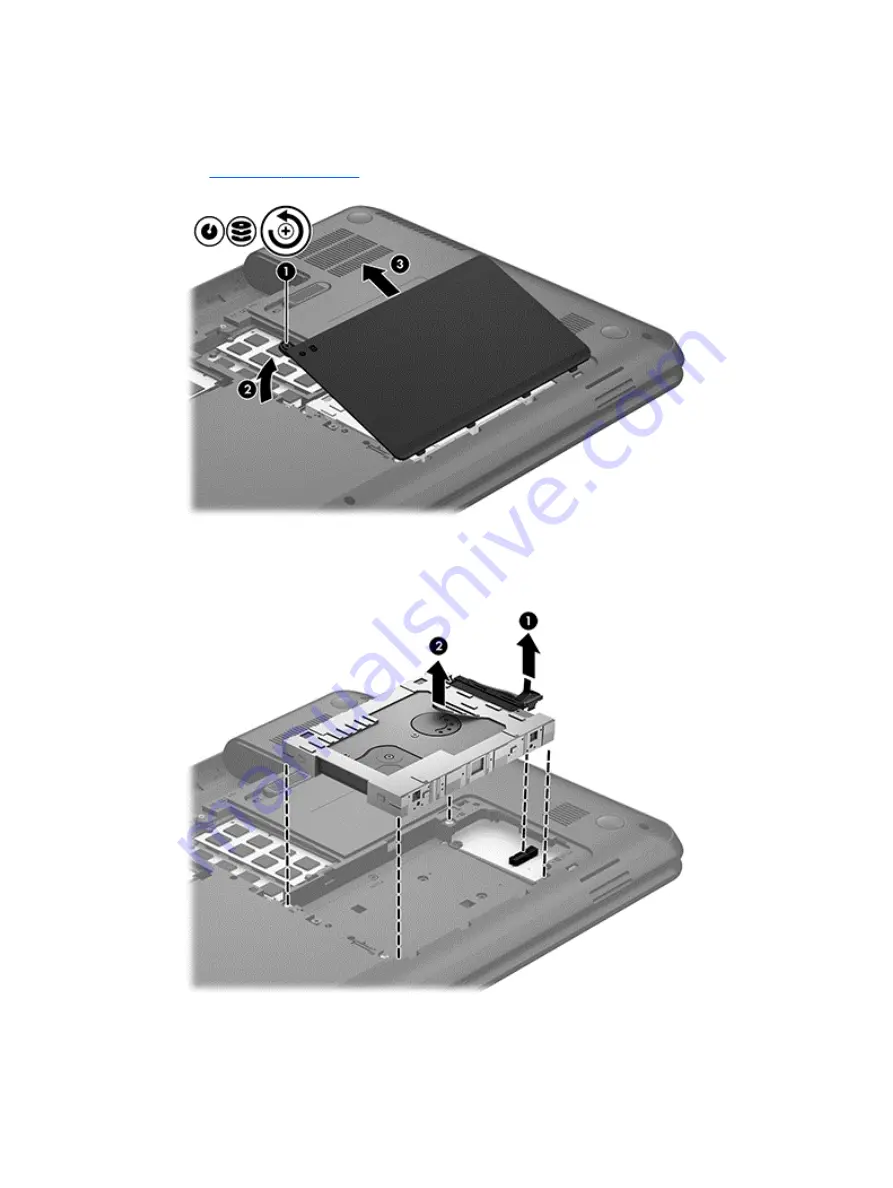
2.
Disconnect the hard drive cable
(1)
from the system board.
3.
Lift the hard drive
(2)
out of the hard drive bay.
4.
Turn over the hard drive, then disconnect the hard drive cable
(1)
from the hard drive.
5.
Pull the sides of the hard drive bracket
(2)
out and away from the hard drive.
Component replacement procedures
71
Summary of Contents for 240 Series
Page 4: ...iv Safety warning notice ...
Page 38: ...3 Illustrated parts catalog Computer major components 30 Chapter 3 Illustrated parts catalog ...
Page 66: ...4 Remove the display bezel 3 58 Chapter 4 Removal and replacement procedures ...
Page 68: ...b Disconnect the module cable from the module 60 Chapter 4 Removal and replacement procedures ...
Page 105: ...d Disconnect the module cable 3 from the module Component replacement procedures 97 ...