background image

coloured blue or black. The
GREEN/YELLOW lead should be
connected to the EARTH terminal
which may be marked with an 'E' or
coloured green or green/yellow. 

• If an extension cable is required, this
should be connected to the end of the
unit cable using a weatherproof
connector. The joint must be positioned
in a suitable weatherproof housing.
The extension cable should be of 3 core
0.75mm2 Polychloroprene rubber
insulated cable (ref: HO5 RN-F) and
permanently wired to the mains supply
with a 3 or 5 Amp fuse. 

• The unit cable (and extension cable)
should be positioned and adequately
protected against damage especially
where contact with gardening
equipment (lawn mowers, forks etc.)
children and domestic animals may
occur. 

• CONSULT A QUALIFIED ELECTRICIAN
OR LOCAL AUTHORITY IF IN ANY
DOUBT ABOUT WIRING TO THE MAINS
SUPPLY. 

Position - 

Construct a solid and level

platform on which to place the
EasyClear™. The platform should be
greater than 300 mm (12") below the
water level. For depths between
300mm and 600mm use the fountain
stem extension segments (Fig 1-F),
which simply screw together, to allow
the fountain to be above the water
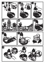
level. For general installation see Fig 4
A/B.  When using the EasyClear for a
waterfall the entire unit should be
submersed.

Connection - 

Place the unit next to the

pond and route the cable back to the
mains supply. Ensure that you allow for

enough cable for positioning the
product in the desired location in the
pond.

Bell Fountain (Fig 1).

Locate the Bell Support (B) to the Bell
Main Body (C) and push fully home.
Position the Bell (D) to the Body
Assembly and press into the central
location

.

2 and 3 tier fountain display assembly
(Fig 1-E). 

The plastic discs that create the 2 and 3
tier water displays simply snap onto the
fountain stem.  Push the fountain stem
into the fountain stem extension
segment and screw onto the fountain
outlet (Fig 1-A).

(Fig 4-A for general installation guide)

Please note: The product has a water
by-pass to control water flow rates
which means a quantity of water will
always come out of the product just
below the flow control. This is normal
in operation.

Position the unit in the pond. The
fountain angle can be adjusted to be
vertical using the ball joint (Fig 2-A).
The tightness of the ball joint can be
adjusted (Fig 2-J)

If required, the 2-Tier Fountainhead
can be used to achieve an alternative
and higher display pattern than the 3-
Tier. 

The fountain height can be adjusted to
suit your needs by rotating the
Fountain Flow Adjuster.  (Fig 3-K) 

Fountain Only

Operation

Accessory Assembly

Installation

Summary of Contents for EASYCLEAR 3000

Page 1: ...2823 3003 EASYCLEAR 3000 Hozelock Ltd Midpoint Park Birmingham B76 1AB England Tel 44 0 121 313 1122 info hozelock com www hozelock com 33854 002 ...

Page 2: ...1 4A 3 5 6 7 4B 8 2 P P O N L M Q R S J K G C E D B A I F H ...

Page 3: ...V X Y V V Z Z W W 10 9 U T 10A ...

Page 4: ...11 5 3 2 4 1 ...

Page 5: ... the ball joint Fig 4A L DO NOT OPERATE THIS UNIT WITHOUT THE OUTER CAGE ATTACHED USING THE UNIT WITHOUT THE OUTER CAGE MAY INVALIDATE YOUR WARRANTY The clear tube inside the unit is made from quartz glass and care should be taken during installation and maintenance We recommend the use of eye protection and suitable gloves The EasyClear 3000 is fitted with a 5W UVC lamp Exposure to Ultra Violet U...

Page 6: ...UPPLY BEFORE PUTTING YOUR HANDS IN THE WATER WHILST EQUIPMENT IS BEING INSTALLED REPAIRED MAINTAINED OR HANDLED Do not use the supply cable to lift the unit as this may cause damage We recommend fitting a lifting cord to the hook feature on the base when the filter is installed in deep water Fig 1 H Check that the voltage marked on the unit corresponds to the mains supply A 10mA OR 30mA RESIDUAL C...

Page 7: ...en using the EasyClear for a waterfall the entire unit should be submersed Connection Place the unit next to the pond and route the cable back to the mains supply Ensure that you allow for enough cable for positioning the product in the desired location in the pond Bell Fountain Fig 1 Locate the Bell Support B to the Bell Main Body C and push fully home Position the Bell D to the Body Assembly and...

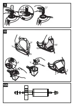
Page 8: ...casionally it will become necessary to clean or replace parts Refer to the safety sections before attempting any maintenance Fountain Head Fig 1 I Follow the below procedure if the fountain head is blocked 1 Place a coin or similar in the slot and gently lever off the fountain head 2 Rinse in clean water and reassemble Foam Follow the below procedure if flow appears reduced 1 Release the Foam Cove...

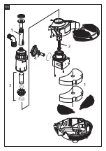
Page 9: ...f the two o rings on the Quartz Tube Assembly Fig 11 3 If these are damaged in any way or you can not guarantee a water tight seal contact Hozelock Consumer Services Biological Filter Normally there is no need to remove the biomedia as any cleaning may kill the colonies of bacteria that make toxic waste harmless 1 Remove the foam 2 The bag of Kaldnes Biomedia Fig 7 P can be removed for cleaning 3 ...

Page 10: ...uns for 12 months after purchase provided that You have followed the installation and operating instructions You are using equipment of the correct size and stocking level for your pond You consult our Helpline 44 0 121 313 1122 early enough for any problems to be put right The product has been returned undamaged A refund can only be authorised by Hozelock Cyprio and is made at the place of purcha...

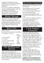
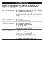
Page 11: ... white flap inside pump chamber moves freely e Ensure rotor is clean and moves freely POOR FOUNTAIN DISPLAY a As above b Clean the Fountain Head UV LAMP NOT WORKING a Check power supply is on b Check fuse RCD and wiring c Replace the lamp d The Overload Protection may have operated see Overload Protection section PUMP NOT WORKING a Check power supply is on b Check fuse RCD and wiring c Check the r...

Page 12: ...Hozelock Ltd Midpoint Park Birmingham B76 1AB England Tel 44 0 121 313 1122 info hozelock com www hozelock com 33854 002 PLEASE NOTE Do not dispose of in household waste ...

Reviews: