background image

4.6 

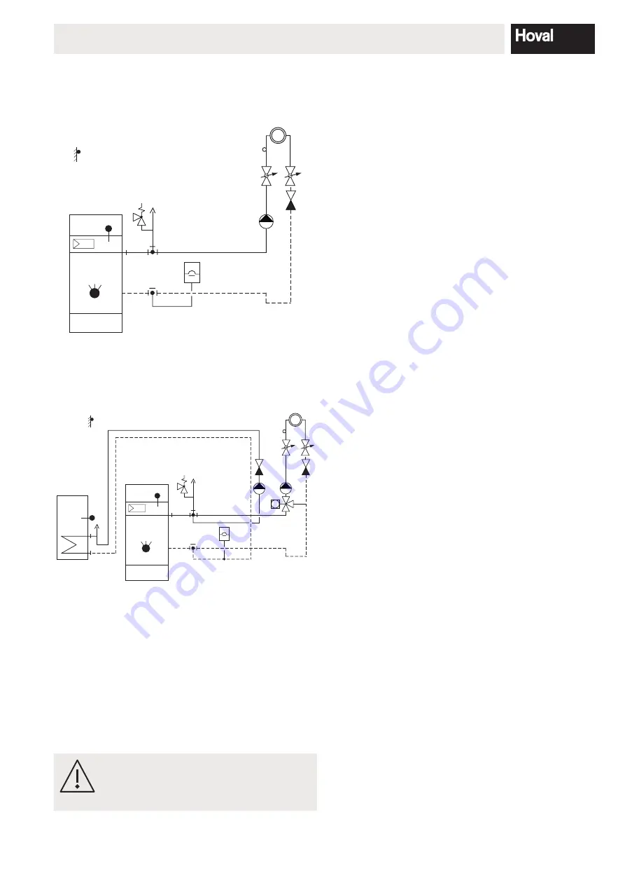
Hydraulic integration

Examples

Direct heating circuit

Fig. 40

Mixer circuit and water heater

M

Fig. 41

4.7 

Condensate discharge

The boiler condensate drain must be made of corrosion-

resistant material.

The following materials are suitable for the condensate 

drain:

 - PVC

 - PE

 - PP

 -

ABS

The minimum inner diameter of the con-

densate drain must be 15 mm. The con-

densate  drain  must  be  sufficiently  in

-

clined

.

A:

A:

it is not necessary to neutralise condensate 

from an oil-fired condensing unit of up to 120 

kW drained together with domestic waste 

water from a private household.

CH:

For the UltraOil

®

, the fuel used must be heat-

ing oil EL low-sulphur. As a rule, neutrali-

sation of the condensate is not necessary. 

Local regulations pertaining to condensate 

discharge must be observed.

D:

For the UltraOil

®

, the fuel used must be heat-

ing oil EL low-sulphur. Neutralisation is there-

fore unnecessary. Regarding the discharge 

of condensate, the local regulations and the 

ATV (Sewage Engineering Association) data-

sheet must be observed.

4.8 

Setting the temperature regulators

Basic setting of the controller is carried out by the heating 

contractor. Selection and setting of the various heating 

programmes in accordance with the operating manual.

4.9 

Safety valves

The heating system and hot water system must each be 

protected with one safety valve against unauthorised high 

pressures. The discharge capactiy of the valves must cor-

respond with the boiler’s maximum nominal heat output. 

The valve must be installed in the flow line in the immedi

-

ate vicinity of the boiler.

4.10  Charging pump (boiler with water heater)

Speed of rotation and output must correspond to the re-

quirements of the water heater. Setting carried out by the 

heating installation engineer.

4.11  Heating pump

Speed of rotation and output must correspond to the re-

quirements of the system. They are to be set by the heat-

ing installation engineer.

25

4 210 255 / 02

INSTALLATION

Summary of Contents for UltraOil 16

Page 1: ...nstallations may only be carried out by a qualified electrician The UltraOil heating boiler is suitable for and approved as a heating unit for hot water systems with permitted flow temperatures up to...

Page 2: ...3 Dimensions UltraOil 16 35 18 3 4 Space requirement UltraOil 16 35 19 4 Installation 4 1 Boiler room requirements 20 4 2 Flue gas connection and chimney 20 4 2 1 Project planning instructions 20 4 2...

Page 3: ...kage testing 33 6 4 Servicing the neutralisation installation if fitted 34 6 4 1 Procedure for servicing the neutralisation installation 34 6 5 Safety temperature limiter Reset 35 6 6 Resetting the fa...

Page 4: ...irective TRD 721 Safety equipment to safeguard against ex cess pressures safety valves for group II steam boil ers DVGW TRGI Technical regulations for gas installa tions DVGW process sheet G600 VDI 20...

Page 5: ...on taminated operating materials gas water combustion air unsuitable chemical additives to the heating water improper handling faulty installation unauthorised modi fications and damage due to the use...

Page 6: ...agonal nuts Fig 01 Using a spirit level set the boiler in longitudinal and trans verse direction and position it with a slight forward tilt This is done by adjusting the nuts on the boiler feet After...

Page 7: ...the stop turn it through 15 so that the projection hangs under the screw head Fig 06 Fig 05 Screw head Fig 06 6 Fix the burner in position by tightening the screw 3 Fig 03 Insulate the cavity between...

Page 8: ...be connected to the boiler with the standard plug in connection The burner cable must be shortened so that the plug in connection has to be parted to swing out the burner 4 5 Cable outlet to the left...

Page 9: ...densate discharge into lower drain line Drain optionally on the left or right side Fig 09 Possibility 2 see chapter 2 5 Execution with Neutralisation box For condensate discharge in lower drain line i...

Page 10: ...condensate tray 4 and tighten securely connection must be sealed 4 Slide the siphon support 3a under the siphon 2 3 5 5a 4 3a Fig 14 5 Fit drain 5 on siphon 3 and lead it outwards op tionally left or...

Page 11: ...owards the front 2 2a 3 Fig 16 3 Remove base plate 3 Fig 16 Lift base plate straight upwards and remove 4 5 Fit rear cover 4 fFig 17 of the neutralisation box 6 Fit jubilee clip 5 approx 20mm from the...

Page 12: ...Fig 16 and front cover 2a 10 Fig 21 Before commissioning the neutralisation box must be filled with water in order to prevent flue gas leakage The condensate drain must be made of corrosion resistant...

Page 13: ...isation granulate front 2 Fig 24 3 Remove front cover 2a Fig 25 Release lateral locking bolt 1 Fig 22 turn approx to the left and pull out as far as the stop Lift the front cover straight upwards and...

Page 14: ...28 7 Fig 28 10 Slightly loosen the jubilee clip 8 Fig 29 and push it upwards Firmly tighten the jubilee clip connection must be sealed 8 Fig 29 11 Fill the neutralisation box with water 12 Fit the fro...

Page 15: ...2 8 Fitting the flue gas silencer Option The silencer must be installed vertically The maximum permissible angle of inclination is 45 Fig 31 15 4 210 255 02 ASSEMBLY...

Page 16: ...directives standards We hereby declare that the product described as an in dividual unit complies with the standards guidelines and technical specifications listed Directives 92 42 EG Efficiency direc...

Page 17: ...or 3 5 3 5 3 5 3 4 Hydraulic resistance at 10 K mbar 6 6 10 6 16 6 30 6 Hydraulic resistance at 20 K mbar 1 7 2 6 4 2 7 7 Water flow rate at 10 K m3 h 1 38 1 74 2 18 3 00 Water flow rate at 20 K m3 h...

Page 18: ...afety flow R1 2 Low temperature return R1 3 High temperature return R1 4 Flue gas outlet DN80 5 Boiler controller 6 Condensate drain left or right incl siphon DN25 and 2 m PVC continuous flow tube inn...

Page 19: ...erviceposition vorne Kesselreini gung von rechts A optimum 300 mm Burner service position left boiler cleaning from the front A minimum gap of 160 mm is required to the right of the boiler without fit...

Page 20: ...fitted an appropriate allowance must be added so that the free cross section area reaches the amount given above 4 2 Flue gas connection and chimney 4 2 1 Project planning instructions The flue gas m...

Page 21: ...g must be observed Hoval UltraOil must only be operated with heating oil EL low sulphur with sulphur content 50 ppm 0 005 It is recommended that you clean the oil tank before refilling it A residual a...

Page 22: ...ol box Danger of cuts and pinching in the area of the trim strip A Wear gloves Grip the switch control box by the left and right sides not by the un derside 1 Schalld mmhaube 1 Fig 23 abnehmen dazu se...

Page 23: ...y it be possible to connect such equipment Fuse Boiler room emergency switch Heat generator Boiler room lighting and pwer sockets must be in a separate circuit Fig 39 3 The fresh air sensor must not b...

Page 24: ...n flow 30 C 70 80 90 100 30 40 50 60 70 14 16 18 20 C kW 70 80 90 100 30 40 50 60 70 14 16 18 20 C kW UltraOil 25 Flow 80 C return flow 60 C Flow 40 C return flow 30 C 70 80 90 100 30 40 50 60 70 15 1...

Page 25: ...ere fore unnecessary Regarding the discharge of condensate the local regulations and the ATV Sewage Engineering Association data sheet must be observed 4 8 Setting the temperature regulators Basic set...

Page 26: ...The pH value of the heating water should lie between 8 3 and 9 5 after 6 12 weeks of heating operation Filling and replacement water For a plant using Hoval boilers untreated drinking water is general...

Page 27: ...filled with water 5 5 Oil burner Setting the burner must also be carried out by a specialist and the setting must correspond to the heat demand of the system Please see the technical information asse...

Page 28: ...it possible only with H Gen without minimum H Gen temperature e g condensing boiler Start PRESS HC level Parameters 13 16 H GEN level Parameter 4 Characteristic heating curve Enable HC Activate Instal...

Page 29: ...6 17 18 19 20 21 22 23 24 25 26 t TAGE 55 45 35 25 Funktionsheizen und Belegreifheizen START 1 2 3 4 5 6 7 8 9 10 11 12 13 14 15 16 17 18 19 20 21 22 23 24 25 26 TAGE 55 45 35 25 3 Funktionsheizen und...

Page 30: ...water tempera ture since the hot water temperature can exceed the temperature setpoint Emissions metering E SS O Immediate end PRESS SHORTLY Remaining time display REACTIONS for emissions metering Ti...

Page 31: ...or remove siphon trap 7 Fig 43 siphon base section 8 fig 38 siphon support 8a or neutralisation box 9 Fig 44 Danger flue gas escaping through the si phon can endanger lives poisoning The siphon page...

Page 32: ...1 2 3 4 5 Fig 42 10 9 6 10 8 6 7 Mount hose for wet cleaning Design with condensate discharge Design with neutralisation box if fitted Fig 43 Fig 44 8a 32 4 210 255 02 MAINTENANCE...

Page 33: ...Hoval Art No 6022 844 Before removing the drain hose all dirt particles must be adequately rinsed out of the condensate drip tray Do not use wire brushes or any sharp objects for cleaning Ensure that...

Page 34: ...in control switch to 0 Remove the front cover Undo the bolts and withdraw the neutralisation box Remove the neutralisation granules and any deposits from the neutralisation box Any remaining neutralis...

Page 35: ...ure rises too high 100 C the system is switched off by the safety temperature limiter by means of a mechanical lockout Press the reset button on the control panel first remove the cover the boiler is...

Page 36: ...rt build up on the heating surface Burner output setting too high Operation without jet inserts 6 6 2 Flue gas temperature limiter reset if no flue gas sensor is fitted If the flue gas temperature ris...

Page 37: ...0 3 5 Heating curve MC2 1 0 OFF 0 20 3 5 Daytime target temperature HC 20 C 5 30 C Daytime target temperature MC1 20 C 5 30 C Daytime target temperature MC2 20 C 5 30 C Night time target temperature H...

Page 38: ...2 Cycle 3 Cycle 1 Cycle 2 Cycle 3 from to from to from to from to from to from to from to from to from to Mo Tu We Th Fr Sa Su Mixer Circuit 1 Time program P1 Time program P2 Time program P3 Tag Cycl...

Page 39: ...1 HF 4 Limit temperature for summer disconnection 22 C HF 5 System frost protection 3 C HF 6 Demand contact module for VE1 1 HF 7 Demand contact module for VE2 1 HF 8 Demand contact module for VE3 1...

Page 40: ...me out OFF 30 min HF 20 PI reference value control OFF HF 21 PI amplification factor P portion Xp 0 1 K OEM 22 PI scanning time Ta 20 s OEM 23 PI reset time Tn 600 s C OEM UNMIXED CIRC Par Designation...

Page 41: ...tion abatement heating circuit 0 8 K HF 15 Pump follow on 5 min HF 16 Screed function OFF HF 18 P portion Xp 2 0 K OEM 19 Scanning time Ta 20 s OEM 20 I portion Tn 270 s OEM 21 Running time servomotor...

Page 42: ...tion abatement heating circuit 0 8 K HF 15 Pump follow on 5 min HF 16 Screed function OFF HF 18 P portion Xp 2 0 K OEM 19 Scanning time Ta 20 s OEM 20 I portion Tn 270 s OEM 21 Running time servomotor...

Page 43: ...portion Xp 5 K OEM 20 Modulation scanning time Ta 20 s OEM 21 Modulation adjustment time Tn 180 s C OEM 22 Modulation running time 12 s HF 23 Modulation starting time 200 s HF 24 Modulation start up...

Page 44: ...on 2 HF 7 Heat generator cycle lock only when parameter 06 1 3 4 0 5 h HF 8 Solar priority parallel changeover 10 K HF 9 Solar heat balance OFF HF SOLAR RESET Reset heat balance HF 11 Volumetric flow...

Page 45: ...Par Designation Factory 10 20 30 40 50 Lev 1 Bus address central device 10 HF 2 Bus right RS direct circuit 1 HF 3 Bus right RS mixer circuit 1 1 HF 4 Bus right RS mixer circuit 2 1 HF BUFFER Par Des...

Page 46: ...MAINTENANCE ST 1 for X days 7 HF 12 Maintenance according to fixed date OFF HF 13 Maintenance according to fixed interval OFF HF 14 Maintenance according to maintenance counter OFF HF 15 Reset mainte...

Page 47: ...on KVLF 19 0 System Collector sensor Short circuit KVLF 19 1 System Room sensor RS Interruption 20 0 System Room sensor RS Short circuit 20 1 System Burner 1 No switching off 1 min 30 2 With par log a...

Page 48: ...tpoint 85 4 System HP return sensor Return max temp exceeded 85 5 System QF Heat source min temp below setpoint 86 4 System QF Heat source max temp exceeded cooling operation 86 5 System QF Fault heat...

Page 49: ...49 4 210 255 02...

Page 50: ...ype Serial number Year of manufacture Place Date System installer System user Confirmation The user owner of the system herewith con rms that he has received adequate instruction in the operating and...

Reviews: