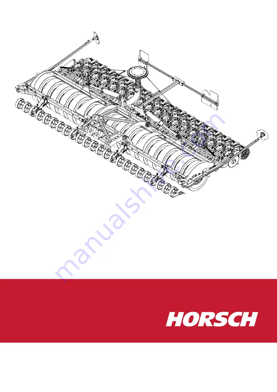
OPERATING INSTRUCTIONS
Taro 6 HD
60029922 • 1 • 09/2020 • en
TRANSLATION OF THE ORIGINAL OPERATING INSTRUCTIONS
READ CAREFULLY PRIOR TO STARTING UP!
KEEP OPERATING INSTRUCTIONS IN A SAFE PLACE!
Page 1: ...OPERATING INSTRUCTIONS Taro 6 HD 60029922 1 09 2020 en TRANSLATION OF THE ORIGINAL OPERATING INSTRUCTIONS READ CAREFULLY PRIOR TO STARTING UP KEEP OPERATING INSTRUCTIONS IN A SAFE PLACE ...
Page 2: ......
Page 3: ...pling 14 2 7 4 Hydraulics 14 2 7 5 Overhead lines 15 2 7 6 Technical limiting values 15 2 7 7 Use in the field 16 2 7 8 Changing equipment wear items 16 2 7 9 Fertiliser and dressed seed 16 2 7 10 Environmental protection 17 2 7 11 Retrofitting and conversions 17 2 7 12 Spare parts 17 2 7 13 Care and maintenance 18 2 8 Danger zone 19 2 9 Safety stickers 20 2 9 1 Positions of safety stickers 22 3 C...
Page 4: ...Tightening torques on the PowerDisc coulter 42 8 Setting the drilling depth 43 8 1 Drilling depth 43 8 1 1 Fine adjustment 43 8 2 Coulter pressure 44 8 3 Correlation 45 9 Setting the bout markers 46 9 1 Adjusting the aggressiveness 47 10 Optional equipment 48 10 1 Crossbar 48 10 2 Track loosener 49 11 Pneumatic system 50 11 1 Hose assembly 50 12 Disposal 51 12 1 Decommissioning 51 13 Care and main...
Page 5: ...Table of contents 60029922 1 09 2020 en 5 14 Tightening torque 58 14 1 Metric screws 58 14 2 Inch screws 59 ...
Page 6: ...res in its sole responsibility as manufacturer that the following product Sämaschine Type Taro 6 HD conforms with the relevant fundamental health and safety requirements of the EC directive 2006 42 EC Schwandorf 07 09 2020 Klaus Winkler Dokumentationsbevollmächtigter Philipp Horsch Hubertus Bultmann Geschäftsführer Leiter Forschung Entwicklung ...
Page 7: ... of machine Please enter the corresponding data into the following list upon reception of the machine Serial number Machine type Year of construction Initial use Accessories Dealer address Name Road Place Phone Cust No Dealer Cust No HORSCH ...
Page 8: ...tive and regular maintenance and inspection Transport Trained personnel of our service and sales partners will provide orientation on how to operate and maintain the machine By submitting the acknowledgement of receipt proper acceptance of the machine is considered confirmed The warranty period starts with the date of delivery We reserve the right to alter illustrations as well as technical data a...
Page 9: ...t notes Instructions for actions and their elements are marked by different symbols ü Prerequisites for instructions for actions 1 Instructions for actions alternative and in warning notes arrow tips ð Intermediate results of instructions for action ð Final results of instructions for action 2 Keep the order of the instructions The designations right left front and rear apply as seen in travel dir...
Page 10: ...g with the machine in public road traffic the respective national registration and traffic law must also be complied with Any other kind of use of the machine contradicting the above is considered not as intended especially connecting attachment to an agricultural tractor that is not suitable attachment to an agricultural working machine not suitable for this purpose operating the machine while pe...
Page 11: ...applicable road traffic regulations and is in possession of a valid driving permit for road travel Ø A person being instructed must only work with or on the machine under the supervision of an experienced person The owner of the machine must Regulate the area of responsibility competence and monitoring of personnel Train and instruct the personnel Make the operating instructions accessible for the...
Page 12: ...e eyes against dust or spray when working with fertil iser or liquid fertiliser Observe the regulations given by the fertiliser manufacturer Respirator masks and protective gloves when handling dressing or dressed seed Ob serve the safety data sheets of the dressing manufacturer Determine the personal protective equipment for the corresponding work assign ment Provide effective protective equipmen...
Page 13: ...technical data are decisive for the design dependent top speed Ø Always match the travel mode to the road conditions to avoid accidents and damage to the undercarriage Ø Consider your personal abilities carriage way traffic sight and weather condi tions 2 7 Safety in operation 2 7 1 Commissioning The operational safety of the machine cannot be guaranteed without orderly per formed commissioning Th...
Page 14: ...mage to the machine if operated incorrectly Escaping fluid may penetrate the skin Hydraulically supported machine parts may drop Hydraulic components may be flung away Pressurised hydraulic hoses may whip about when detaching them Ø Connect the hydraulic hoses to the tractor only when the hydraulics on tractor and machine are depressurised Ø Lower all hydraulically lifted parts e g wings packer un...
Page 15: ...g electric currents pace voltage 1 Do not leave the cabin 2 Do not touch any metal objects 3 Do not create a conductive connection to ground 4 Warn persons DO NOT come near the machine Electric voltages at the ground can cause severe electric shock 5 Wait for professional rescuers The overhead power line needs to be switched off If persons need to leave the cabin despite the voltage flashover e g ...
Page 16: ...s have only been designed for forward travel in the field and may be damaged when re versing 2 7 8 Changing equipment wear items Ø Only pulling tools may be attached that meet the technical requirements ac cording to these operating instructions HORSCH does not assume any liability for damages resulting from the attachment of non fitting pulling tools as well as incorrect mounting Ø For machines w...
Page 17: ...by HORSCH for this purpose Ø Comply with country specific regulations for weights weight distribution and dimensions For equipment influencing the weight or weight distribution the regulations con cerning towing facility support and axle load must be checked and complied with For machines without brakes a brake system may need to be retrofitted if the per missible weight limits are exceeded In cas...
Page 18: ...sible to the welding point Ø Before cleaning the machine with high pressure cleaner cover all openings which should stay clear of water steam or cleaning agents for reasons of safety or operation Do not aim the water jet directly on electric or electronic components or bearings When cleaning with high pressure cleaning equip ment or steam jet always keep a distance of at least 50 cm to machine com...
Page 19: ...ts can lower slowly and unnoticed Failing to pay attention to the danger zone can result in severe or even fatal physical injuries 1 Do not stand under lifted loads Lower such loads to the ground first 2 Instruct persons to leave the danger zone around the machine and tractor be fore any machine movements 3 Before working in the danger zone of the machine or between machine and tractor Shut down t...
Page 20: ...ty stickers must be replaced immediately 3 Affix the specified safety stickers on spare parts 00380054 No passengers are allowed to ride on the machine 00380055 Before commissioning the machine the operating instruc tions must be read and followed 00380133 Caution for fluids spraying out under high pressure follow the notes in the operating instructions 00380135 Stay clear of the operating range o...
Page 21: ...off the key before starting maintenance and repair work 00380299 Do not climb on rotatable parts Use mounting steps provided for this purpose 00381116 Secure the machine with wheel chocks before uncoupling or parking 00381117 Keep sufficient safety distance to the slewing range of the machine ...
Page 22: ...nsibility 22 60029922 1 09 2020 en 2 9 1 Positions of safety stickers The positions of the safety stickers depend on the equipment Safety stickers with the addition 2x can be found on either side of the machine 2x 2x 2x ...
Page 23: ... a tractor or needs to be lifted off with suitable lifting gear forklift truck or crane Ø Use only lifting equipment and lifting gear with adequate lifting capacity and approval Ø Points with the associated stickers Strapping point must not be used for load suspension When using other lifting points pay careful attention to the centre of gravity and the weight distribution These points must in any...
Page 24: ...e machine will be carried out by our service engineers or distributors Any preceding use of the machine is prohibited The machine can only be released for operation after the instruction session conduc ted by service technicians or sales partners and after the operating instructions have been read WARNING Increased danger of accidents during commissioning Ø Observe the notes in the Safety chapter ...
Page 25: ... Length m 3 38 Weight kg 4 300 4 700 NOTE Deviations due to technical further development reserved The weight of the implement depends on the equipment specification with minimum equipment The permissible transport heights and transport width for road traffic may differ from country to country Comply with the national registration regulations Taro 6 HD ...
Page 26: ...age is manufactured Year of manufacture on the type plate Time of final production of the machine in the respective equipment version Due to processes there may be some periods between the manufacturing of the ba sic vehicle and final production There may be differences therefore with the spe cification of the year of manufacture 4 3 Requirements on the tractor WARNING Risk of accident from overlo...
Page 27: ...HD min kW HP 200 max kW HP 250 4 3 1 Calculating the ballasting The permissible total weight the permissible axle loads and the tyre load bearing ca pacity must not be exceeded when mounting or connecting implements The front axle of the tractor must always be loaded with at least 20 of the curb weight of the tractor Ø Check before road transport whether the tractor used is suitable for this imple...
Page 28: ...owing applies to towed machines d 0 x Information of tractor manufacturer for minimum rear ballasting If no in formation is available enter 0 45 All specified weights in kg All specified dimensions in m The centre of gravity of the machines cannot be specified exactly because of optional equipment Enter half the machine length for calculation Calculations 1 Calculation of minimum front ballasting ...
Page 29: ...onnected machine to determine the front and rear axle load Compare the determined values with the calculated values This includes permissible total weight maximum front and rear axle load minimum front axle load 20 of the tractor s curb weight The calculated values must not exceed the permissible values Actual value as calculated Permissible value from operating instructions Two times the permissi...
Page 30: ...22 1 09 2020 en 5 Design 5 1 Overview 1 2 3 4 5 6 7 8 Taro 6 HD 1 Lighting 2 Distributor tower 3 Tyre packers 4 Implement attachment 5 Hydraulic cylinders for flaps 6 Crossbar 7 Bout marker 8 TurboDisc seed bar ...
Page 31: ...es Symbols on the handles of the hydraulic couplings indicate the function of the re spective hoses Folding Crossbar Bout marker NOTE The following hydraulic movements are carried out via the hoses marked with Lift Folding Retraction of cultivation tools Fan flow ...
Page 32: ...ders Limbs may be pinched or crushed by unintentional retraction of the piston rods Ø Park the machine to attach or remove the clips with the parking brake pulled Ø Order persons to leave the area of the tractor cab Ø Make sure when placing or removing clips that the control units are not oper ated by any other person Ø Lock control units mechanically or electrically depending on the version CAUTI...
Page 33: ...l light C 3 Lamp blinker Number Designation Colour Function 1 L yellow Blinker left 2 54 g 3 31 white Earth 4 R green Blinker right 5 58 R brown Rear light right 6 54 red Brake light 7 58 L black Rear light left WARNING Traffic accidents caused by defective lighting Ø Ensure cleanliness and tight fit of the plug and socket connections Ø Check the lighting before driving off Ø Check warning boards ...
Page 34: ...ANGER Serious accidents from loss of stability Ø Park the machine only on a level and firm ground Ø Secure the machine against rolling away before unhitching Ø Always park the machine while unfolded NOTE Ø Check all plug and socket connections hydraulic electric and pneumatic for cleanliness and firm seating Dirty connectors will contaminate the flowing media The connectors there fore become worn ...
Page 35: ...cally or electrically depending on the version during transport travel Never switch them to the floating position Ø Check all interlocks before starting to drive Ø Check whether all securing elements of the connection are in place as set cor rectly Ø Check components of the connection for wear Ø Make sure that the transport height lies below the maximum permissible transport height adjust the tran...
Page 36: ...d NOTE Ø Clean the machine and prepare properly before parking it for an extended period see chapter Care and Maintenance Ø Thoroughly clean hopper and fertiliser equipment Fertiliser is aggressive and speeds up the corrosion process It especially attacks galvanised components like bolts Ø Clean all metering units Ø Preferably park the drill in a shed so that no moisture can accumulate in hop per ...
Page 37: ...he danger zone around the machine Make sure be fore folding that no persons are present in the danger zone Ø Comply with the accident prevention instructions WARNING Risk of accident due to insufficient stability Ø Fold the machine only after it has been fully connected Ø The machine must not be in an inclined position when folding it Ø Fold the machine only on a level and firm surface CAUTION Dam...
Page 38: ...ow The press roller 6 guides the coulter in depth and ensures closing of the soil The harrow 7 covers the seed furrow with soil and calms the flow of soil The coulter body is mounted in maintenance free rubber bearings 1 It links the coulters and the press roller and transfers the coulter pressure 7 2 Coulter discs The coulter discs are arranged at the front at an angle with slight pretension to e...
Page 39: ...r on the coulter discs or the discs will no longer have contact Ø In this case replace the coulter discs and adjust the preload by removing the washer again Always remove the shims in pairs at the left and right under the coulter disc bearing Tighten the screws for the coulter disc bearings socket head cap screw M 16 x 1 5 with 130 150 Nm Tighten the screws for the coulter discs 6 x M 8 each with ...
Page 40: ...raper should not rub against the clean press roller at any point 7 2 6 Uniformer The uniformer firms the seed in the seedbed and presses it gently down Under moist conditions and sticky soils the uniformer may pick up residues It should then be removed NOTE Ø To avoid damaging the uniformers do not reverse with the machine lowered 7 2 7 Press rollers The press rollers guide the depth of the seed p...
Page 41: ...rque is 100 Nm each NOTE Ø Set the press roller to the upper position for deep seed placement This aligns the coulter horizontally 7 2 8 Rubber mounting NOTE Ø Keep the rubber mounting free of oil Oils and grease can harm the rubber and thus adversely affect the function 7 2 9 Harrow The height and angle of attack of the harrow can be adjusted if necessary 1 Ø Adjust the height Unscrew the screw 1...
Page 42: ...adjust the scraper on the press rollers if required Ø Check the scrapers and uniformers for condition tight fit and adjustment Ø Check coulter discs and bearings for wear light movement and preload Ø Tighten the screws for the coulter disc bearings M 16 x 1 5 with 130 150 Nm Tighten the screws for the coulter discs 6 x M 8 each with 38 Nm Ø Check the rubber mounting and replace if aged or showing ...
Page 43: ...ly during use 8 1 Drilling depth The coulters are guided in the depth via the press rollers Two options are provided for depth setting Basic setting via the press roller itself Follow the press roller section in this re gard Fine adjustment using aluminium clips on the adjustment rods 8 1 1 Fine adjustment The coupling bars are connected via a square tubing section The distance to the seed bar and...
Page 44: ...hen starting work and regularly during use 8 2 Coulter pressure The harder the soil and the deeper the seed is to be placed the higher the required coulter pressure If the coulter pressure is too high the frame is lifted up slightly via the press rollers or the press rollers sink into the soil Exact depth guidance is therefore no longer en sured Adjusting the coulter pressure Ø Set the coulter pre...
Page 45: ...th but also the coulter pressure and the press rollers Changes to the coulter pressure ad justment mainly effect coulters and press rollers but also have an influence on the drilling depth Ø Check the coulter pressure in the field after each change of drilling depth Ø Check the drilling depth in the field after each change of the coulter pressure ...
Page 46: ...t time the bout markers must be set to working width Marking takes place in relation to the centre of the tractor The adjustment length of the bout markers measured from the middle of the outer most row results from half the working width plus half the row distance Row spacing m Working width m b Length of bout marker m l 0 16 3 00 1 58 0 16 4 00 2 08 0 16 6 00 3 08 0 16 8 00 4 08 b b l ...
Page 47: ...adjustment 1 Adjust the aggressiveness of the bout markers according to the soil conditions 2 To do so loosen the hexagon screws A adjust the bout marker disc by turn ing the offset rod and retighten the hexagon screws A 3 Check the working pattern of the bout marker in the field and correct if re quired ...
Page 48: ...ylinders are connected in series on either side Ø In order to assure synchronism of the cylinders and perfect adjustment of all piston rods to the end stop all cylinders should be completely extended before starting work Ø The angled plate can be adjusted to the intended aggressiveness In case of wear it can be renewed or readjusted CAUTION Exceeding the permissible transport width Risk of damages...
Page 49: ...he tines into the soil without damaging them Ø Set the track loosening tines to the top position if necessary 2 1 3 Track loosening tines Adapting tines to the tractor Ø Adapt the tines to the track width of the tractor To do so loosen the screws on the flange 1 slide the tines to the desired po sition and fasten the screws again Adjusting the working depth Ø Loosen the cotter pin 2 and pull it ou...
Page 50: ... 1 09 2020 en 11 Pneumatic system 11 1 Hose assembly Verteilerausgang Schar Fahrtrichtung Pneumatic hose assembly row spacing 167 mm Verteilerausgang Schar Fahrtrichtung Pneumatic hose assembly row spacing 250 mm ...
Page 51: ...tely For the waste disposal of auxiliary and operating media as well as other chemicals the specifications in the respective safety data sheets must be strictly complied with 12 1 Decommissioning If the machine is no longer suitable for use and needs to be disposed of it must be decommissioned All machine parts must be separated by material and passed on to environmentally friendly waste disposal ...
Page 52: ...erating conditions Prior to delivery the machine was checked at the factory and by the HORSCH sales partner to ensure the optional condition of the machine To maintain troublefree operation it is important to carry out the care and mainten ance work at the recommended intervals 13 1 Maintenance overview The maintenance intervals are determined by various factors Different conditions of use weather...
Page 53: ...ary Hydraulic hoses Hydraulic hoses must be replaced after 6 years Pay attention to the manufacturing date on the crimp sleeve year month and the hose quarter year for this purpose Hose Crimp sleeve Depending on the conditions of use e g weather influences or in case of higher strains on the machine the hoses may need to be replaced earlier Have the hydraulic system checked by an expert at least o...
Page 54: ...ced tensioning force 40 h Coulter discs Check state wear bearing play and light movement The discs must be rotatable by hand 40 h Press rollers Check for condition tight fit and wear prior to use Scrapers on coulters and press rollers Check for condition tight fit and wear prior to use Harrow Check condition firm seating setting and wear prior to use Pneumatic system Hydraulic connections and hose...
Page 55: ... the machine Ø Clean the machine thoroughly at regular intervals and after the end of the sea son Ø Wear the necessary protective outfit when performing any work to protect your health and safety Ø Clean the outside of the machine with water Open the fall sluice under the metering unit so that entered water can flow off Ø Clean the volume metering unit distributor and hoses of the pneumatic sys te...
Page 56: ...10 Unplug the terminal and store it in a dry place 13 4 Lubricating the machine Ø Lubricate the machine regularly and after each wash with a suitable grease gun This ensures operability and reduces repair costs and downtimes CAUTION Handling lubricants Lubricants and mineral oil products are no danger to health as long as they are used as instructed Ø Avoid prolonged skin contact or the inhalation...
Page 57: ...ints Taro 6 HD 13 5 Packer 1 Check the packer bearings for firm seating 2 Check the packer shafts for free rotation 3 Lubricate the packer bearings at regular intervals 4 Check packer segments for wear deformation and breakage 5 If so equipped adjust the scrapers as needed ...
Page 58: ...nuts 4 8 5 8 8 8 10 9 12 9 3 0 50 0 9 1 1 1 8 2 6 3 0 4 0 70 1 6 2 0 3 1 4 5 5 3 5 0 80 3 2 4 0 6 1 8 9 10 4 6 1 00 5 5 6 8 10 4 15 3 17 9 7 1 00 9 3 11 5 17 2 25 30 8 1 25 13 6 16 8 25 37 44 8 1 00 14 5 18 27 40 47 10 1 50 26 6 33 50 73 86 10 1 25 28 35 53 78 91 12 1 75 46 56 86 127 148 12 1 25 50 62 95 139 163 14 2 00 73 90 137 201 235 14 1 50 79 96 150 220 257 16 2 00 113 141 214 314 369 16 1 5...
Page 59: ... Coarse thread Fine thread 1 4 6 4 5 6 6 3 8 6 9 8 12 2 13 5 5 16 7 9 10 8 12 2 17 6 19 0 24 4 27 1 3 8 9 5 20 3 23 0 31 2 35 2 44 7 50 2 7 16 11 1 33 9 36 6 50 2 55 6 70 5 78 6 1 2 12 7 47 5 54 2 77 3 86 8 108 5 122 0 9 16 14 3 67 8 81 3 108 5 122 0 156 0 176 3 5 8 15 9 95 0 108 5 149 1 169 5 216 0 244 0 3 4 19 1 169 5 189 8 271 1 298 3 380 0 427 0 7 8 22 2 176 3 196 6 433 9 474 5 610 0 678 0 1 2...
Page 60: ...60 60029922 1 09 2020 en Notes ...
Page 61: ......
Page 62: ...All details on technical specifications and illustrations are approximate and non binding Subject to technical product revisions ...