background image

MAN1175-01-EN

Indianapolis, USA  |  Cork, Ireland  |  Calgary, Canada  |  Bangalore, India  |  Oakleigh, Australia  |  Tianjin, China  |  Esteio, Brazil

Please visit our website for a complete listing and to learn more about certified Horner Automation products.
This document is the property of Horner Automation Group, and is subject to change. 

page 3 of 8

  3 WIRING

The OCS-I/O HE959CNX16 Base should be powered independently from the power supplied to the OCS-I/O modules themselves. This 
offers optimum noise immunity and helps maintain galvanic isolation between the CsCAN Network and I/O Power. The recommend-
ed approach is to power the CsCAN network from one power supply, and I/O devices from at least one separate power supply. The 
OCSIO bases are powered from the CsCAN Network. Horner OCS controllers do not supply 24VDC to the V+ connection of the CsCAN 
network.

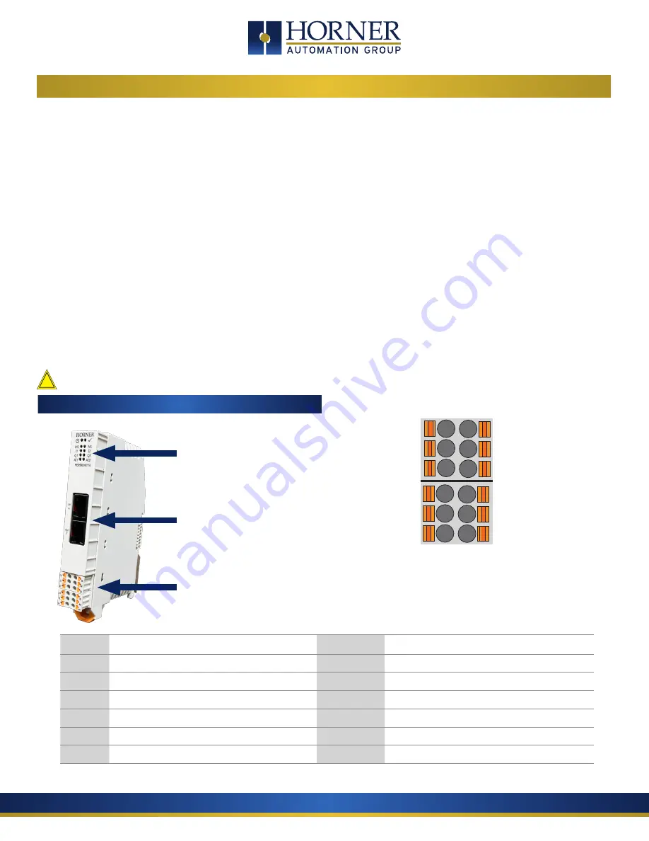
To power the HE959CNX116, use bottom six pin connector. 

For network wiring, the recommended approach is to daisy-chain each node, with a continuous connection for shield. The center pin 
of the CAN port does not provide a connection to earth ground. The cable shield should be connected to earth ground at one location 
only – usually at the DC supply powering the network. The network DC supply should have its V- terminal connected directly to earth 
ground.

If multiple DC supplies are used to power the network, the V+ from any one supply should be connected only to nodes it is powering 
– disconnected from other sections powered by other supplies. The V- connection should be continuous across the entire network, 
although V- should connect to earth at exactly one point only.

At each end of the network, a 121

, 1/4W, 1% resistor should be used for termination – installed between the CAN_H and CAN_L ter-

minals. Only appropriate Thin (for <100m) or Thick (<500m) cabling should be used (assuming 125 KBaud) available from a variety of 
sources.  . 

         Use 75°C copper conductors only.

SIGNAL LABEL

DESCRIPTION

SIGNAL 

LABEL

DESCRIPTION

AI1a

1a

Universal Analog Input “a”

AI1b

1b

Universal Analog Input “b”

AI1c

1c

Universal Analog Input “c”

GND

0V

Digital and Analog Ground

I1

I1

Digital / Analog Input 1

Q1

Q1

Digital Output 1

I2

I2

Digital / Analog Input 2

Q2

Q2

Digital Output 2

VEXT

V1

V+ Input for Digital Output

AQ1

AQ

Analog Output

24V

V+

V+ Input for Power

GND

0V

Digital and Analog Ground

1a *

1c *

I1
I2

V1

V+

1b *
0V
Q1
Q2
AQ
0V

  Onboard Wiring 

Onboard I/O


CAN Port - IN

CAN Port - OUT

LED Indicators


See page 6

*WARNING: 

Do not put voltage on 1a and no more than 

12V on 1b or 1c ports.  Doing so will damage the board.  

!

Summary of Contents for HE959CNX116

Page 1: ...es 0 10V 0 20mA 4 20mA 0 60mV 0 10V 0 20mA 4 20mA 0 60mV 16 Bit AI Full Scale 0 20 Thermocouple J K T N E R S B Converter Type 16 Bit ADC RTD PT100 PT1000 RTD Excitation Current 250mA 1 4 Digital Outputs Inputs per Module 2 Commons per Module 1 Output Type Sourcing with 10kΩ pull down Absolute Max Voltage 28VDC Output Protection Short Circuit Max Output per Point 2A Max Total Out Current 4A Max Ou...

Page 2: ...ld be followed in the installation of this product b Shielded twisted pair wiring should be used for best performance c Shields should be grounded at one end only preferably at the end providing the best noise shunting SAFETY PART NUMBER HE959CNX116 TECHNICAL SUPPORT For assistance and manual updates contact Technical Support at the following locations North America Europe 317 916 4274 353 21 4321...

Page 3: ...uts Digital Analog Number of Channels 2 Digital or Analog Configured as Analog I O Analog Input Ranges 4 20mA 0 10V Analog Input Data Ranges 0 4000 2000 2000 0 1000 0 32000 Alarm Value Register Configured to Digital Inputs Digital Input Ranges 24V 12V 5V Custom Input Voltage Range 0 24VDC Absolute Max Voltage 30VDC Input Impedance 10kΩ Custom Digital Input Ranges Threshold ON Threshold OFF OFF to ...

Page 4: ...only usually at the DC supply powering the network The network DC supply should have its V terminal connected directly to earth ground If multiple DC supplies are used to power the network the V from any one supply should be connected only to nodes it is powering disconnected from other sections powered by other supplies The V connection should be continuous across the entire network although V sh...

Page 5: ...Q 0 10V Analog Out 10VDC 4 20 mA Analog Out OV AQ 20mA Digital Analog In 24V 12V 5V Custom Current Mode I1 0V 20mA Digital Out Positive Logic vs Negative Logic Wiring The OCS can be wired for positive or negative logic inputs 0V I1 0V I1 Positive Logic In Negative Logic In 0 10VDC Voltage Mode I1 0V Universal Analog Input 1a 1b 1c 0 10VDC NC 0 10V Analog In 1c 1a 1b 60mV 60mV mV In NC Thermocouple...

Page 6: ...D of each base Status Register Location where fifteen consecutive words are reported Digital Inputs Digital Outputs Analog Inputs Analog Outputs Start starting locations for each type of I O for this base Be careful to choose starting addresses that do not conflict with OCS built in I O mapping Comm Timeout Maximum amount of time the HE959CNX116 will wait to act on a communications timeout 40 to 2...

Page 7: ...guration mismatch error of each IO Modules Module 1 to Module 8 IOE Each bit bit9 bit 16 represents IO modules error Module 1 to Module 8 WDG TRIP IO base watchdog trip count IOCS Each bit bit9 bit 16 represents IO modules calibration status Module 1 to Module 8 PUP Power up error sticky bit OFFLINE OCSIO is offline DI1 US High when Digital input 1 is in undefined state DI2 US High when Digital in...

Page 8: ... ON Flash 1Hz OCS Run Mode ON ANY ANY ANY Onboard I O Fault ON OFF ON ON Invalid Dynamic Configuration ON Flash 1Hz ON ON Power Up Waiting to be Configured ON ON Flash 1Hz Flash 1Hz LED Indicators for Individual I O Channels I1 Digital Input 1 active I2 Digital Input 2 active Q1 Digital Output 1 active Q2 Digital Output 2 active AI1 Analog Input Active AQ1 Analog output Active NOTE Channel LED wil...

Reviews: