background image

Plumbing the Valve to the Tank (Continued) 

       

           

                  
                     


                   

www.hornblasters.com


[email protected]

Securing the horn to the Mounting Bracket

L

o

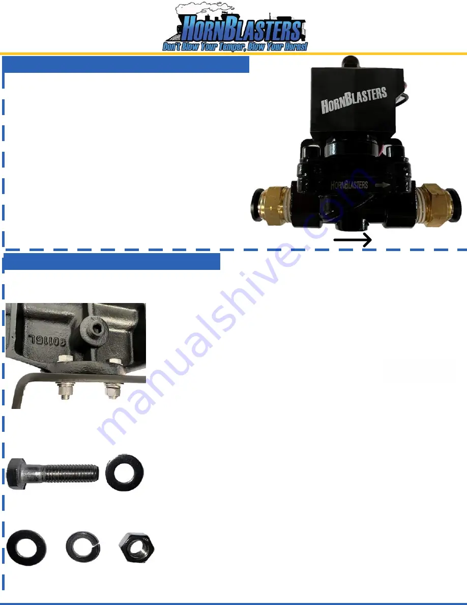
cate  the  solenoid  valve  for  your horns. Take note of 

the arrow on the side of  the  body  of the  valve.  This 

arrow  must  point  TOWARDS  your horns.  If  the valve 

is  mounted  with  the arrow pointing towards the tank, the 

valve will not hold air pressure and leak 

instantly

Locate 

two of the four 1/2" NPT x 1/2" PTC fittings that 

came with your kit.

 Plumb 

each

 fitting into the air valve. 

Use a wrench to tighten the fitting snug. Be careful not to 

apply pressure to the plastic portion of the fitting. It can 

break. 

Grab the 1/2" line that we plumbed into the tank and route 

it up to this valve. Insert the line into the 1/2" fitting on the 

inlet portion of the valve.

Locate the

 horn mounting bracket as we need to secure the horn to this mount before it can be plumbed to the 

solenoid valve. The image below shows what the hardware looks like when assembled.

Start by positioning the horn manifold over the bracket so that the four 

mounting holes line up. You will need the following hardware:

4x - 3/8" Threaded Bolt

8x - 3/8" Flat Washer

4x - 3/8" Split Lock Washer

4x 3/8" Nut

Start by feeding a bolt through one of the flat washers (figure 1). Move 
the washer all the way up to the head of the bolt. Route the bolt/washer 
combo down through the horn manifold and horn bracket.
On the bottom of the bracket, feed a flat washer and split lock washer 
over the bolt thread. Make sure the split lock washer is on the bottom of 
the stack (figure 2). 

Thread the nut onto the bolt and use a 9/16" wrench to tighten it up. You 
will need another wrench on the bolt head to tighten the nut up

 later

The split lock washer will compressor when full tightened. Repeat this 
process for all four mounting points to secure the horn to the mounting 
bracket. 

Leave these bolts loose for now, as we still need to plumb the 

inlet fitting into the horn. Leaving the bracket loose makes the next step 
much easier.

Figure 1

Figure 2

Flat washer  - Split Washer   -   Nut

Page 11

Summary of Contents for NATHAN AIRCHIME

Page 1: ...ANUAL ULTIMATE NATHAN AIRCHIME KIT WARNING To ensure the longevity of your system reading and following these instructions are recommended Make sure to change filters and to drain the moisture from your tank on a regular basis Page1 ...

Page 2: ... 1x Analog Pressure Gauge 4x 40A 12v Relays 4x HornBlasters 1NM Compressor 1x Electric Drain Valve Kit 1x Digital Air Pressure Gauge 1x Tire Inflation Kit 4x 8 Gauge Universal Wiring Kit 1x Nathan Airchime K5LA Train Horn 12 Gallon Air Tank 1x Nathan Airchime Mounting Bracket 3x 1 4 Brass Run Tee 4x Compressor Mounting Bracket 4x 22 Roll of 8 18 Gauge Wire Page2 ...

Page 3: ...or explosive materials or where aerosol products are being used Do not operate this product where oxygen is being administered Do not pump anything other than atmospheric air Never use this product while sleepy or drowsy Do not use any tools or attachments with the supplied air source unit without first determining maximum air pressure for that tool or attachment Never point any air nozzle or air ...

Page 4: ...erminal connectors to better seal them up against the elements Loctite 545 Thread Sealant Can be used instead of Teflon to seal fittings Hardware Specifications K5LA Hardware o Bell to Manifold 3 8 16 x 1 1 2 Bolt o Bell Back cap 1 4 20 x 7 8 Bolt o K5LA Horn to Mounting Pedestal 3 8 16 x 1 1 2 Bolt Compressor Hardware o Compressor Mounting Hardware 10 32 x 1 Bolt A longer bolt can be used o Compr...

Page 5: ...ount the bells to the manifold make sure to insert an O ring into each bell s inlet to ensure a proper seal The image below on the left shows this step Make sure that the O ring is firmly seated into the groove on the bell This prevents excess air from escaping before it enters the horn and makes a sound Secure each horn bell to the manifold using a bolt lock washer on each side of the horn bell T...

Page 6: ...Assembling the Horn Common Horn Configurations Standard 2 Bells Reversed 3 Bells Reversed Page6 ...

Page 7: ...ld pressure Do not use this for anything other than the filter Connect fittings to compressor filter Route 3 8 air line in between filter compressor Filter Placement Your compressor is fully sealed against the elements If the compressor is mounted outside with the air filter on the end of the compressor the filter will get wet and water will get pulled into the compressor To prevent this the filte...

Page 8: ...h to the tank so that the leader hoses from each compressor can connect into the tank If you need to mount the four compressors further away from the tank we sell fittings that can be used to extend the hose on the compressor Try to mount the compressors in a dry area if possible this helps the compressors last longer and prevents the finish from tarnishing over time Be careful when handling the c...

Page 9: ...ght If you plan to mount the tank upside down an elbow will be need to relocate the pressure switch When mounting upside down the pressure switch and elbow fitting on the bottom will be reversed switch sides and the pressure switch is too tall to clear the legs of the tank if you mount this on a flat surface Right End Port Left End Port Safety Blowoff Valve Outlet fitting for 1 2 line to horns 1 2...

Page 10: ...ut of the fitting This can cause the fitting to leak over time Take a larger bend further away from the fitting to prevent the line from stretching the fitting out These fittings can be re used with the same line multiple times If you need to remove the line follow these steps Plumbing the Air Valve to the Tank Compressors 1 2 Compressors 3 4 Route the leader hose from each compressor into each ru...

Page 11: ...elow shows what the hardware looks like when assembled Start by positioning the horn manifold over the bracket so that the four mounting holes line up You will need the following hardware 4x 3 8 Threaded Bolt 8x 3 8 Flat Washer 4x 3 8 Split Lock Washer 4x 3 8 Nut Start by feeding a bolt through one of the flat washers figure 1 Move the washer all the way up to the head of the bolt Route the bolt w...

Page 12: ...bracket If you source your own hardware for this install we would recommend a minimum bolt size of 3 8 for this horn Once the horn has been mounted to the vehicle you can plumb the horn to the air valve from page 11 Simply press the line into the PTC portion of the elbow fitting Makes sure the line is routed carefully and away from any heat sources The line will melt if it is too close to your exh...

Page 13: ... Display voltage of battery fuction Turn ignition key to run display battery voltage for 60 sec Display fucton Display air pressure value number and led color will correspond Air Pressure Sensor Installation instructions Black air press sensor wire black Green air press sensor wire green Brown air press sensor wire brown Do not over tighten sensor 12 14 ft lbs Air Pressure Gauge Installation instr...

Page 14: ...ing into the inlet side of this solenoid valve The outlet is the port the arrow faces towards so this fitting will be plumbed on the port opposite the direction the arrow faces Inlet Outlet Locate the 3 8 NPT x 1 4 FNPT reducer bushing that was packed with the other drain valve components Go ahead and thread this fitting into the outlet of the valve or the side the arrow points towards This will s...

Page 15: ...Quad Compressor Wiring Diagram Page15 ...

Page 16: ...Connecting the Train Horns to the Steering Wheel Connecting the Train Horns to a Push Button Page16 ...

Page 17: ...Page17 ...

Reviews: