10
EN
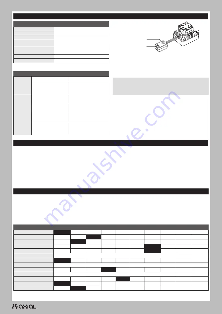
Programmable Item
Option 1
Option 2
Option 3 Option 4 Option 5 Option 6
Option 7
Option 8
Option 9
Option 10
1. Running Mode
F/R
F/R/B
2. Cutoff Voltage
Disabled
Low
Medium
High
3. RPM/ Throttle Matching
Low
Medium
High
4. Max. Forward Force
25%
37.5%
50%
62.5%
75%
87.5%
100%
5. Max. Reverse Force
25%
37.5
50%
62.5%
75%
87.5%
100%
6. Turbo Timing
0° – 10°, Adjustable in 1° Increments (0° Default)
7. Turbo Delay
Off
0.1s
0.2s
0.3s
0.4s
0.5s
8. Drag Brake Force
50% – 200%, Adjustable in 5% Increments (Default: 80%)
9. Drag Brake Rate
Level 1
Level 2
Level 3
Level 4
Level 5
Level 6
Level 7
Level 8
Level 9
Auto
10. Neutral Range
6% –17%, Adjustable in 1% Increments (Default: 10%)
11. Start Mode (Punch)
Level 1
Level 2
Level 3
Level 4
Level 5
Level 6
Level 7
Level 8
Level 9
12. BEC Voltage
6.0V
7.4V
13. Motor Rotation
CW
CCW
Blacked out cells with white lettering represent the default settings.
ESC PROGRAMMING
PROGRAMMING THE ESC WITH THE OPTIONAL SPMXCA200 SMART PROGRAMMER BOX
1. Connect the programming box to the switch.
2. Connect a battery to the ESC.
3. Power on the box and select the parameter with the SELECT button.
4. Change the values of the selected parameter with the EDIT button
5. Press the SAVE button to save the changes. The ESC requires a
power cycle to implement the saved changes.
SPECIFICATIONS
Dimensions (L × W × H)
47mm × 36mm × 24mm
Weight
4 oz (113.4g)
Max Current
120A
Voltage Range
Voltage Range
2-4S Lipo
Servo Output Voltage
(BEC)
6 or 7.4V selectable,
Continuous current of 6A
Battery Input Connector
IC5
®
(EC5
™
compatible)
Motor Connectors
5mm Bullet
* Default setting for low voltage cutoff is Li-Po.
ESC OPERATION
TRANSMITTER AND ESC CALIBRATION
The transmitter throttle neutral, forward and brake/reverse positions must be calibrated prior to ESC operation. To calibrate the transmitter and ESC:
1. Power on the transmitter.
2. Connect a fully charged battery to the ESC.
3. Press and hold the ESC power button.
4. Release the button when the red LED on the button flashes. The
red LED on the ESC will start to flash.
5. With the transmitter trigger in the neutral position, press the
ESC power button to store the neutral position. The green LED
on the ESC will flash once and the motor will emit a single tone,
indicating the neutral position has been stored.
6. Pull the transmitter trigger to full throttle, and press the ESC power
button. The green LEDon the ESC will flash twice, and the motor will
emit two tones, indicating the full throttle position has been stored.
7. Push the transmitter trigger fully forward to the full brake/reverse
position, and press the ESC power button. The green LED on the
ESC will flash three times and the motor will emit three tones,
indicating the brake/reverse position has been stored.
The ESC and motor can now be operated normally.
ESC MOTOR PAIRING
In the event the motor has been subjected to a severe impact, is
overheating or has abnormal power output, use the following process
to automatically pair the motor to the ESC:
1. Disconnect the throttle lead from the receiver.
2. Remove the pinion gear from the motor.
NOTICE:
Do not attempt to pair the ESC and motor without
removing the pinion gear from the motor. Failure to remove the
gear may result in the vehicle accelerating unexpectedly as well as
incorrect pairing.
3. Connect a fully charged battery to the ESC.
4. Press and hold the power button. The red LED on the power button
will flash, followed by a short double flash that repeats after
approximately eight seconds.
5. Release the power button.
6. The motor will automatically rotate and the green LED on the ESC
will flash. When the motor stops, the green LED will glow solid,
indicating the pairing process is complete.
7. Power off the ESC.
8. Install the pinion gear to the motor.
9. Connect the throttle lead to the receiver.
LED STATUS
INDICATION
Normal
Operation
Red and Green LEDs off
Throttle is at neutral
Red LED glows solid
Throttle is moved away
from neutral, either forward
or reverse/brake
Error
Codes
Red LED single flashes
continuously
Low voltage cutoff
activated
Green LED single flashes
continuously
ESC thermal protection
activated
Green LED double flashes
continuously
Motor thermal protection
activated
Red and Green LEDs flash
continuously
Sensor error. Check
the motor sensor wire
connection
Programming port
Power button


