


EN
RV-7 1.1m
8
Eratix 3D Flat Foamy 860mm
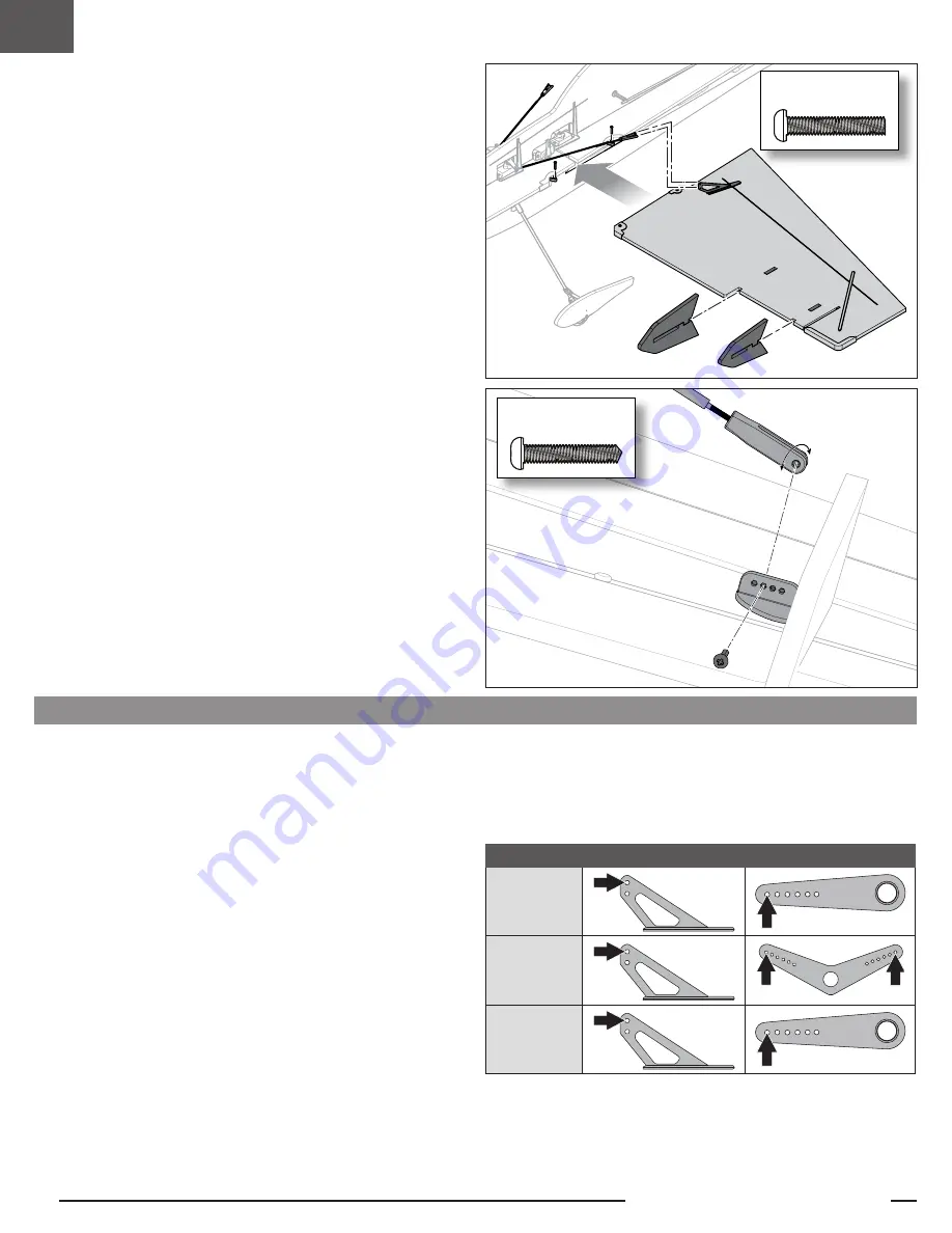
Control Horn and Servo Arm Factory Settings
The table to the right shows the factory settings for the control horns and servo
arms. Fly the aircraft at factory settings before making changes.
After flying, you may choose to adjust the linkage positions for the desired control
response. See the table to the right.
Horns
Arms
Elevator
Ailerons
Rudder
Wing Installation
Mount the Wing to the Fuselage
1. Insert the carbon fiber spar into the fuselage.
2. Slide the left wing onto the spar, with the control horn facing up, until it seats
into the fuselage mounting structure.
3. Install two M2 x 8mm screws into the front and rear wing mounts.
4. Install the aileron pushrod Z-bend into the outside hole of the aileron servo arm.
Connect the clevis to the aileron control horn outside hole, and slide the clevis
retainer into place.
5. Repeat Steps 2–4 for the right wing.
Install the Side Force Generators on the Wings
IMPORTANT:
The larger side force generators are located on the wing inboard.
The smaller side force generators are located on the wing outboard.
IMPORTANT:
Install the top and bottom of the side force generator correctly,
matching each to the wing color scheme.
1. Carefully flex the side force generators to the side and slip them onto the wing,
parallel
with the wing.
2. As they get close to the holes in the wing, rotate them vertically and set them
into place.
3. Repeat Steps 1 and 2 for the other wing.
TIP:
For a more secure fit, add a drop or two of glue on the top and bottom of the
side force generators to lock them into place.
Install the Optional Wing Struts
IMPORTANT:
Optional-use wing struts are provided with the model. We
recommend using them for aggressive flying or with higher-capacity batteries.
1. Using an M2 x 8mm self-tapping screw, install the wing strut to the fuselage.
2. Rotate the forked clevis on the other end of the strut until its holes align
perfectly with one of the holes in the multi-hole wing mount. The wing should
remain flat.
3. Install an M2 x 8mm self-tapping screw.
4. Repeat Steps 1 thru 3 for the other strut.
Optional Wing Struts
After assembly and transmitter setup, confirm that the control surfaces are
centered. The model must be powered, bound to the transmitter in AS3X mode,
with the throttle left at zero. When enabled, SAFE mode is active at power up.
AS3X mode is activated when the throttle is raised above 25% for the first time
after being powered on. It is normal for the control surfaces to respond to aircraft
movement if the aircraft is in AS3X or SAFE modes.
1. Verify the trims and sub trims on your transmitter are zero.
2. Power up the model in AS3X mode and leave the throttle at zero.
3. Look at the tip of each control surface and verify it is mechanically centered.
4. If adjustment is required, turn the clevis on the linkage to change the length of
the linkage between the servo arm and the control horn.
Control Surface Centering
M2 x 8 mm
Machine Screw
M2 x 8 mm
Self-Tapping Screw


