background image

EN

12

PNP Receiver Selection and Installation

The Convergence aircraft is capable of using either the Spektrum

 DSMX

®


serial receiver (SPM4648), included in the BNF aircraft, or a standard 6-channel 
full range (sport) receiver. Refer to your receiver manual for correct installation 
and operation instructions. 

Installation of a DSMX serial receiver

1. Remove the bottom cover from the fuselage. 
2. Mount the receiver to the fuselage as shown using double-sided servo tape 

or hook and loop material.

3. Attach the serial receiver lead to the receiver and to the fl ight control board 

as shown below.

4. Replace the bottom fuselage cover.

Installation of a standard sport receiver

1. Remove the bottom cover from the fuselage. 
2. Mount the receiver to the fuselage as shown using double-sided servo tape 

or hook and loop material.

3. Connect the individual channel jumpers from the fl ight controller to the 

corresponding channels on the receiver as shown below.

4. Replace the bottom fuselage cover.

Flight Controller Connections

Flight Controller Connection

Aileron (Ch2)

Elevator (Ch3)

Throttle (Ch1)

Rudder (Ch4)

Gear (Ch5)

Aux1 (Ch6)

Serial Receiver port

Summary of Contents for CONVERGENCE VTOL

Page 1: ...Instruction Manual Bedienungsanleitung Manuel d utilisation Manuale di Istruzioni ...

Page 2: ...te various levels of potential harm when operating this product NOTICE Procedures which if not properly followed create a possibility of physical property damage AND little or no possibility of injury CAUTION Procedures which if not properly followed create the probability of physical property damage AND a possibility of serious injury WARNING Procedures which if not properly followed create the p...

Page 3: ...mitter Full Range 6 channel 2 4GHz with Spektrum DSMX technology Required Required As of this printing you are required to register with the FAA if you own this product For up to date information on how to register with the FAA please visit https registermyuas faa gov For additional assistance on regulations and guidance on UAS usage visit knowbeforeyoufly org Preflight 4 Transmitter Setup 4 Model A...

Page 4: ...smitter 9 Make sure linkages move freely 10 Perform the Control Direction Test with the transmitter 11 Perform the stability system control direction test with the aircraft 12 Adjust flight controls and transmitter 13 Perform a radio system Range Test 14 Find a safe open area to fly 15 Plan flight for flying field conditions Transmitter Setup The Convergence aircraft requires a transmitter with a minim...

Page 5: ...Take 3 steps away from the aircraft receiver and then power ON the transmitter in bind mode Refer to your transmitter s manual for specific binding instructions 5 The receiver is bound to the transmitter when the LED on the receiver glows solid orange IMPORTANT The flight controller will not arm the ESCs if the throttle is not in the lowest position and the throttle trim at or below center 6 Power c...

Page 6: ...d security apply the loop side soft side of the optional hook and loop tape to the bottom of your battery and the hook side to the battery tray 4 Install the fully charged battery in the battery compartment as shown Secure using the hook and loop strap 5 Connect the battery to the flight controller 6 Keep the aircraft upright immobile and away from wind or the system will not initialize The motor n...

Page 7: ...ht control system is functioning properly Assemble the aircraft and bind your transmitter to the receiver before performing this test CAUTION Keep all body parts hair and loose clothing away from a moving propeller as these items could become entangled Set the transmitter switches to airplane flight stability mode Move the entire aircraft as shown in the table and ensure the control surfaces move i...

Page 8: ... familiarize yourself with the controls prior to attempting your first flight Throttle Throttle Elevator Aileron Rudder Multirotor Flight Airplane Flight Throttle up Throttle up Elevator down Aileron right Rudder right Throttle down Throttle down Elevator up Aileron left Rudder left Climb Left side view Left side view Left side view Rear view Top view Left side view Left side view Left side view Rea...

Page 9: ...aircraft in any orientation The following table gives the switch positions and a brief description of the possible flight conditions available Flight Conditions Multirotor Flight Switch H Position 1 Airplane Flight Switch H Position 0 Stability Mode Switch A Position 0 Limited bank angle Very little pitch change Forward and backward flight is achieved through angling of the main motor nacelles Self ...

Page 10: ...ange the flight attitude switch on your transmitter to the multirotor flight position and stability mode for landing The throttle will increase slightly and the motor nacelles will rotate to the vertical position The tail motor will power on and the elevons will go to neutral While in multirotor flight the elevons do not move All pitch roll and yaw control is accomplished by differential thrust and a...

Page 11: ...or mount 6 Remove the tail motor from the mount and carefully remove the motor wires from the plastic wire clip Assembly is the reverse of the removal process Familiarize yourself with the Flying Your Aircraft section prior to trimming your aircraft Trimming should be done in calm wind conditions and with a fully charged transmitter and flight battery 1 During your first Airplane Flight trim the air...

Page 12: ...pe or hook and loop material 3 Attach the serial receiver lead to the receiver and to the flight control board as shown below 4 Replace the bottom fuselage cover Installation of a standard sport receiver 1 Remove the bottom cover from the fuselage 2 Mount the receiver to the fuselage as shown using double sided servo tape or hook and loop material 3 Connect the individual channel jumpers from the fl...

Page 13: ...C3 plug to the power lead from the flight controller 5 Remove the bottom fuselage cover 6 Thread the video camera connector from the FPV compartment through the fuselage and to the front of the bottom compartment 7 Attach the video transmitter antenna to the video transmitter 8 Mount the video transmitter to the mounting plate provided in the fuselage using either double sided foam tape or self adh...

Page 14: ...Aircraft bound to different model memory ModelMatchTM radios only Select correct model memory on transmitter Flight battery Transmitter battery charge is too low Replace recharge batteries Transmitter may have been bound to a different aircraft using different DSM protocol Bind aircraft to transmitter Control surface does not move Control surface control horn linkage or servo damage Replace or rep...

Page 15: ... aircraft control system and pilot skills have successfully demonstrated all maneuvers intended or anticipated prior to the specific event b An inexperienced pilot is assisted by an experienced pilot 4 When and where required by rule helmets must be properly worn and fastened They must be OSHA DOT ANSI SNELL or NOCSAE approved or comply with comparable standards B RADIO CONTROL 1 All pilots shall a...

Page 16: ...ice you in the event that you may need any assistance For questions or assistance please visit our website at www horizonhobby com submit a Product Support Inquiry or call the toll free telephone number referenced in the Warranty and Service Contact Information section to speak with a Product Support representative Inspection or Services If this Product needs to be inspected or serviced and is com...

Page 17: ...t may cause undesired operation of the device Instructions for disposal of WEEE by users in the European Union This product must not be disposed of with other waste Instead it is the user s responsibility to dispose of their waste equipment by handing it over to a designated collections point for the recycling of waste electrical and electronic equipment The separate collection and recycling of yo...

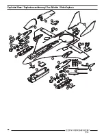
Page 18: ...64 Exploded View Explosionszeichnung Vue Éclatée Vista Esplosa 1 18 2 3 4 8 8 9 10 15 17 16 16 18 12 12 10 19 19 19 19 19 19 19 19 19 19 10 10 11 11 14 21 14 13 7 8 7 6 5 ...

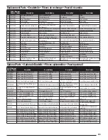
Page 19: ...MW Videosender VTX 200MW Émetteur vidéo 200mW Trasmettitore videoVTX 200 MW SPMVT600 Video transmitter VTX 600MW Videosender VTX 600MW Émetteur vidéo 600mW Trasmettitore videoVTX 600 MW SPMVX5802 RHCP Omni RightAngle Connector RHCP Omni Winkelstecker Antenne omnidirectionnelle RHCP avec prise à angle droit Connettore ad angolo retto RHCP Omni SPMA9556 AirTelemetry Flight PackVoltage Sensor EC3 Flu...

Page 20: ...ered trademarks of Horizon Hobby LLC The Spektrum trademark is used with permission of Bachmann Industries Inc Futaba is a registered trademark of Futaba Denshi Kogyo Kabushiki Kaisha Corporation of Japan All other trademarks service marks and logos are property of their respective owners US 8 672 726 Other patents pending http www e fliterc com Created 09 16 52710 EFL11050 EFL11075 ...

Reviews: