7
S
CANNER
I
NSTALLATION
RS232 (-14)
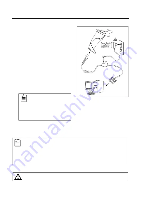
1. Turn off the host device.
2. Plug the 10-pin RJ45 end of the
PowerLink cable into the 10-pin
socket on the scanner. There will be
an audible
click
when the connector
lock engages.
3. Connect the 9-pin D-type connector
of the PowerLink cable to the proper
COM port on the host device.
If the scanner is receiving power from the
host system, skip to step #6.
4. Plug the power supply into the power
jack on the PowerLink cable.
Check the AC in input
requirements of the power
supply to verify the voltage
matches the AC outlet.
The outlet must be located
near the equipment and be
easily accessible.
5. Connect AC power to the transformer.
6. Turn on the host device.
The scanner is shipped from the factory configured to set of default
conditions. Plugging the scanner into a port on the host system does
not guarantee that the scanned information will be communicated
properly to the host device. The scanner and host device
must
use the
same communication protocol. Please refer to the MetroSelect Single-
Line Configuration Guide or the help files provided with MetroSet
2
for
instructions on changing the scanner’s factory default configuration.
See caution on page 6
Figure 5.
Summary of Contents for Voyager GS 9590 Series
Page 1: ...VoyagerGS 9590 Series Single Line Hand Held Laser Scanner User s Guide ...
Page 18: ...14 STANDS Flex Stand Assembly PN 46 00709 Figure 13 Stand Assembly ...
Page 48: ......
Page 49: ......
Page 50: ......
Page 51: ......


