Honeywell Vista Automation Module Installation & Setup Manual Download Page 1

VAM (VISTA Automation Module) - Installation & Setup Guide 

Introduction 

VISTA Automation Module (herein referred to as “VAM”) combines home automation and home security and is intended 
for use with compatible VISTA

®

 series control panels. VAM includes a built-in web server, Wi-Fi

®

 capability, and Z-Wave

®


technology allowing VISTA installations to support Z-Wave devices.  
The VISTA Automation Module also supports Remote Services for controlling Z-Wave devices and Scenes remotely from 
an associated Total Connect™ account. 
VAM is controlled using a web browser on a Wi-Fi enabled smart device such as a Tablet PC, laptop, Smartphone, etc. 

DISPLAY NOTE:

 For optimum viewing of the screens and menus, the tablet’s font size setting may need to be adjusted. 

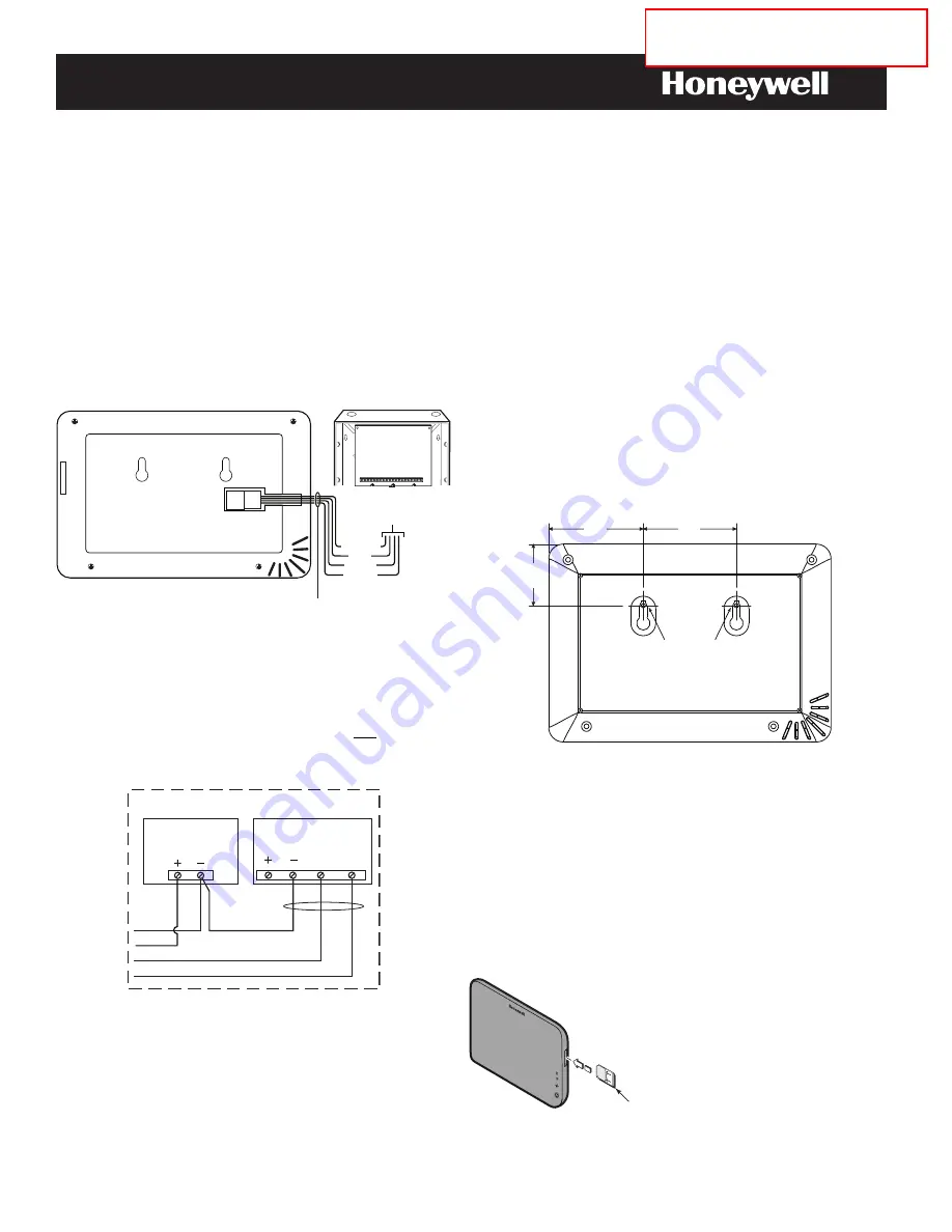
Make Wiring Connections 

Connect VAM to the control panel’s keypad data (ECP) 
terminals using a standard 4-wire keypad connector harness. 

v

am-003-V1

TO

CONTROL PANEL

ECP TERMINALS

YELLOW

RED

BLACK

GREEN

CONTROL PANEL

PC BOARD

VAM

REFER TO THE CONTROL PANEL’S INSTRUCTIONS
FOR MAXIMUM WIRE LENGTHS.

4-WIRE CONNECTOR HARNESS

Wire Connections to the Control Panel 

Verify that VAM and other connected devices do not exceed the 
control’s Aux Power output capability. If it does, use a 
supplementary power supply as shown. 

IMPORTANT:

 When VAM is powered from an auxiliary power 

supply, always apply power to the control panel first and then 
VAM. Failure to observe this sequence results in improper 
operation of VAM and may result in an ECP Error indication. 

pwr_supp_conn-011-V0

BLACK

POWER FROM SUPPLEMENTARY
POWER SUPPLY IF USED

RED 

BLACK

GREEN

YELLOW

CONTROL

TERMINAL STRIP

SUPPLEMENTARY

+12 VDC

POWER SUPPLY

P/N AD12612

DATA

IN

DATA

OUT

AUX AUX

Supplementary Power Connections 

Mount the VAM 

VAM is for indoor use only and should be mounted near the control 
panel or a keypad connected to the control panel for ease of wiring. 

VAM mounts to a wall surface by hanging on two screws. See the 
diagram below. 

Leave the screw heads 1/8” above the wall surface.

If necessary, drill a hole in the wall for the wire harness to pass
through.

Connect the wire harness to the VAM before mounting.

MOUNTING SCREW

DRILL 3/16” DIA. HOLES 2 PLACES

1.65”

2.5”

2.54”

vam-004-V0

Insert an SD/SDHC Memory Card 

An SD card must be installed to receive automatic software 
upgrades. The SD card can be left in the VAM. See Software 
Upgrades section. 

Avoid touching the contacts on the card

4GB SD card supplied

Supports up to 16GB SD Card

Insert the memory card (SD/SDHC Card) as shown.


INSERT

SD CARD

EXHIBIT 

7-1

CFS8DLVAM / 573F-VAM

EXHIBIT 

7-1

PLEASE GO TO THE BOTTOM OF 
PAGE 7 FOR FCC / IC AGENCY 
STATEMENTS.

Summary of Contents for Vista Automation Module

Page 1: ...it does use a supplementary power supply as shown IMPORTANT When VAM is powered from an auxiliary power supply always apply power to the control panel first and then VAM Failure to observe this sequence results in improper operation of VAM and may result in an ECP Error indication pwr_supp_conn 011 V0 BLACK POWER FROM SUPPLEMENTARY POWER SUPPLY IF USED RED BLACK GREEN YELLOW CONTROL TERMINAL STRIP...

Page 2: ...teps must be repeated to connect the VAM to the new router 1 Connect a smart device to VAM a Power up the VAM b Connect the smart device to the VAM using the device s WiFi settings menu VAM is a wireless access point Enter the VAM SSID VAM_xxxx SSID is case sensitive NOTE xxxx the last 4 digits of the MAC address Enter the Key found on the VAM label WPA2 pw line 2 Access VAM s home screen a Open a...

Page 3: ...e or more selected system events or conditions occur NOTE Email notification requires that the user has an active email address 1 Click Setup then select Email 2 Click User SMTP to assign the user s email server information SMTP establishes the email server domain the from address a Choose the email server name email provider from the drop down menu Choose from GMAIL OUTLOOK YAHOO or Add New b Ent...

Page 4: ...on to 320 x 240 8 frames per sec Normal quality 5 Click the Add button if the camera information is not discovered automatically to enter information manually 6 To edit camera information highlight the camera name and click the Edit button Enter required information and then click Save Automation Creating Scenes The system can automatically activate various devices when certain events occur based ...

Page 5: ...l Z wave devices have been tested and some features may produce unpredictable results Using VAM as a Secondary Controller VAM can be used as a secondary controller when connected to another Z Wave network 1 Remove any Z Wave devices previously included in VAM Click Automation Z Wave Setup to display the Z Wave Management screen then click Z Wave Default and select Yes 2 Press the Z Wave Primary bu...

Page 6: ...te access lets the user access VAM s menus directly via the Internet when away from home The home router must first be configured for port forwarding Refer to the router s instructions for details on port forwarding To set up a remote access log in do the following 1 Click Setup Account 2 Enter the desired user name and password Passwords must be a minimum of 8 alphanumeric characters and must inc...

Page 7: ...n for help INDUSTRY CANADA CLASS B STATEMENT This Class B digital apparatus complies with Canadian ICES 003 Cet Appareil numérique de la classe B est conforme à la norme NMB 003 du Canada FEDERAL COMMUNICATIONS COMMISSION FCC PART 15 This device complies with Part 15 of the FCC Rules and RSS 210 of Industry Canada Operation is subject to the following two conditions 1 This device may not cause har...

Reviews: