


FIGURE 6C. INSTALLATION OF MMI-6SF MODULE IN FRONT CHASSIS
POSITION
2
3
1
C0226-01
Step 1: Insert the bottom edge of the MMI-6SF module down into a front slot
of the chassis.
Step 2: Carefully swing the upper edge of the board towards the back of the
chassis until it touches the 1.25˝ (32 mm) standoffs installed on the
rear module.
Step 3: Align two 4-40 screws with the two standoffs and tighten.
Step 4: Address and wire the modules according to the instructions in this
manual.
WIRING
NOTE: All wiring must conform to applicable local codes, ordinances, and
regulations.
NOTE: All references to power limited represent “Power Limited (Class 2)”.
1. Install module wiring in accordance with the job drawings and appropri-
ate wiring diagrams.
2. All wiring to the MMI-6SF is done via terminal blocks. In order to prop-
erly make electrical connections strip approximately 0.25˝ of insulation
from the end of wire, sliding the bare end of the wire under the clamping
plate screw.
3. Set the address on the modules per the job drawing. Use the rotary code
switches to set the address of the first module (between 01 and 154).
In Class B operation, the remaining modules are automatically assigned to
the next five higher addresses. For example, if the base address switch is
set to 28, the next five modules will be addressed to 29, 30, 31, 32 and 33.
The module is shipped in Class B position, remove shunts for Class
A. When operating in Class A, alternate modules are paired together
(+0/+1, +2/+3, +4/+5), resulting in a total of three modules. For
example, if the base address switch is set to 28, then 30 and 32 will be
automatically assigned to the modules while 29, 31 and 33 are available
to be used for other modules on the SLC. For Class A and B operation,
DO NOT set the lowest address above 154, as the other modules will be
assigned to nonexistent addresses.
NOTE: The MMI-6SF must have power cycled for shunt changes to take effect.
NOTE: Some panels support extended addressing. In order to set the
module above address 99 on compatible systems, carefully remove the
stop on the upper rotary switch (see Figure 7). If the panel does not sup-
port extended addressing, do not set the lowest address above 94.
FIGURE 7.
TENS
0
7 8
6
5
4
3
2
1
9
10
11
12
13
14
15
C0227-00
4. A shunt is provided to disable a maximum of two unused modules in
Class B operation and Class A operation. Modules are disabled from the
highest address and work downward. If two modules are disabled, the
lowest four addresses will be functional, while the highest two will be dis-
abled. For example, in Class B operation, if the shunt for Address Disable
is placed on “two” and the base switch is set to 28, the modules will be
assigned to 28, 29, 30 and 31 while disabling the highest two positions.
NOTE: Place unused shunts on single pin to store on board for future use.
NOTE: Power must not be applied to the unit when changing functional-
ity on the shunts.
WIRING NOTES
• Power-limited circuits must employ type FPL, FPLR, or FPLP cable as
required by Article 760 of the NEC.
• All wiring must be in accordance with the NEC, NFPA 72 and all other
applicable codes and standards. All external power supplies must be
power limited with battery back-up. All external power supplies and
detectors must be UL listed for fire protection signaling applications.
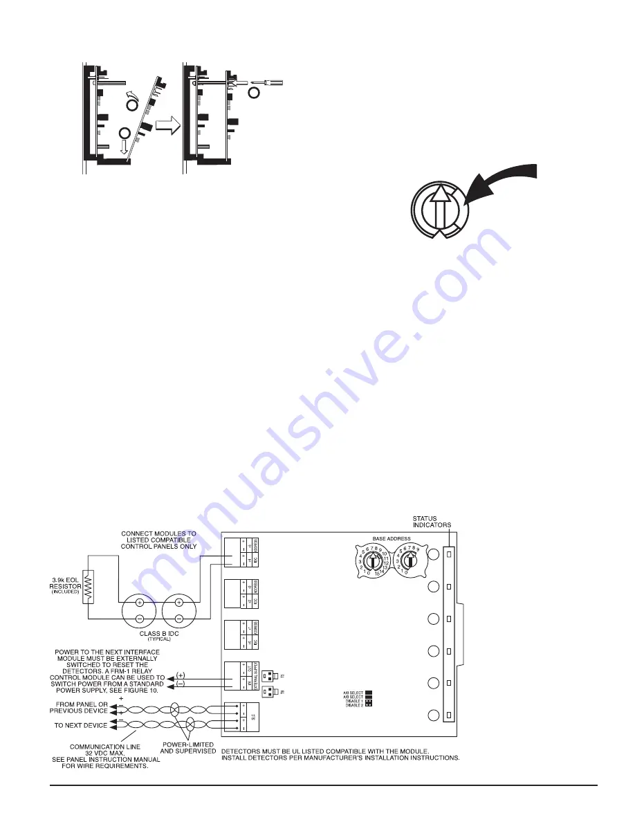
FIGURE 8. INTERFACE TWO-WIRE CONVENTIONAL DETECTORS – CLASS B
To use a common power supply between multiple MMI-6SF modules, connect a long power supply jumper from T5 or T6 to T5 or T6 on the adjacent MMI-6SF.
C0853-00
3
I56-2742-009
7/1/2022