Honeywell V48A Product Data Download Page 9

V48A,F,J; V88A,J DIAPHRAGM GAS VALVES

9

60-2080—9

of the valve flows out through the bleed port. This reduces the 

pressure on top of the diaphragm, allowing the gas pressure 

below to lift the diaphragm and open the valve.

When all the gas has bled off the top of the diaphragm, the 

valve is fully open, permitting gas flow to the main burner.

After the controller is satisfied, the procedure is reversed. The 

controller contacts open so the coil is de-energized. The 

plunger is released, moving to the DOWN position. This 

closes the bleed port and opens the supply port so gas flows 

again into the top port of the valve. As the gas pressure on top 

of the diaphragm increases, the diaphragm begins to close. 

When the pressures on both sides of the diaphragm are 

balanced, the valve will be closed. The weight and spring help 

to close the valve. If the gas supply fails and there is no 

pressure below the diaphragm, the weight and spring will 

close the valve.

In the event of a power failure during automatic operation, all 

V88 and V48 valves will close. Normal operation will be 

resumed upon power restoration.

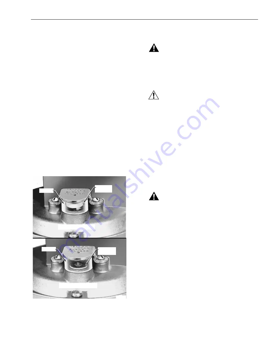
Operation of the Valve Position Indicator 

(Fig. 11)

An optional valve position indicator is available in the 1-1/4 in. 

V48A2227 and 2 in. V48F1103 Valves. When the valve is 

open, a yellow disk shows in the window. When the valve is 

closed, only the black top of the disk is visible.

Fig. 11. Valve position indicator (optional).

CHECKOUT AND TROUBLESHOOTING

WARNING

Explosion Hazard.

Can cause severe injury, death or property 

damage.

Do not allow fuel to accumulate in the combustion 

chamber. If fuel is allowed to enter the chamber for 

longer than a few seconds without igniting, an 

explosive mixture could result.

CAUTION

Equipment Damage Hazard.

Can cause equipment damage and improper 

operation.

1. Do not put the system into service until you have 

satisfactorily completed all applicable tests 

described in the Checkout section of the 

instructions for the flame safeguard control, and any 

other tests required by the burner manufacturer.

2. Close all manual fuel shutoff valves as soon as 

trouble occurs.

Checkout

Start the system and observe its operation through at least 

one complete cycle to be sure the valve functions as 

described in the Operation section.

Troubleshooting

WARNING

Electrical Shock Hazard.

Can cause severe injury or death.

Use utmost care during troubleshooting. Line voltage 

is present at the actuator for a V48 Valve, and is 

present in all controller circuits for all V48 and V88 

Valves.

IMPORTANT:

 Do not assume that the valve must be replaced until 

all other sources of trouble have been eliminated.

If the valve will not open when the thermostat or 
controller is calling for heat:

1.

Check that there is voltage at the valve actuator (black 

leadwires, Fig. 7). Be careful—there should be line 

voltage at the actuator of a V48.

2.

If there is no voltage at the actuator, first make sure line 

voltage power is connected to the master switch, the 

master switch is closed, and overload protection (circuit 

breaker, fuse, or similar device) has not opened the 

power line.

3.

For a V88 only: If a line voltage power is okay, check the 

transformer. Replace it if necessary.

WINDOW

YELLOW

DISC

BLACK TOP

OF DISC

VALVE OPEN

VALVE CLOSED

WINDOW

M18856

Summary of Contents for V48A

Page 1: ...mum closing time V48J V88J rated for 150 F 66 C ambient temperature V48F rated for 5 psi lb per sq in 34 5 kPa V48A and V88A rated for either 1 2 or 1 psi 3 4 or 6 9 kPa depending on model V48J and V88J rated for 1 psi 6 9 kPa One model for natural and LP gases Wide range of sizes and capacities Firm closing diaphragm is both weight and spring loaded Valve closes on power failure recommended for f...

Page 2: ...Body Material Die cast aluminum Pilot Tapping see Table 1 for thread type 3 4 through 1 1 2 inch valves 1 8 27 NPT or 1 8 28 BSP PI 2 through 3 inch valves 1 4 18 NPT Bleed Tapping see Table 2 for thread type 1 8 27 NPT or 1 8 28 BSP PI Valve Opening Time Five seconds maximum at 2 oz in 2 0 86 kPa pressure Adjustable bleed valve assembly or fixed bleed orifices available for longer opening time NP...

Page 3: ... 1 1 2 2 110V 50 Hz V88A 24V 60 Hz 1 2 3 4 3 4 1 1 1 4 1 1 2 1 6 9 3 4 1 1 1 4 1 1 2 2 2 1 2 3 V88J 24V 60 Hz 6 9 1 1 1 4 Valve Size in Valve Opening Time seconds No Orifice Orifice No 122160 0 018 in 0 46 mm Orifice No 124674 0 011 in 0 28 mm 1 1 2 3 1 1 4 1 5 6 1 1 2 1 5 6 2 4 15 32 2 1 2 4 23 37 3 5 24 37 1 2 1 2 BLEED TAPPING 1 8 27 NPT OR 1 8 28 BSP PL PILOT TAPING 2 1 8 27 NPT FOR 3 4 THROUG...

Page 4: ...he same size as the first valve INSTALLATION When Installing This Product 1 Read these instructions carefully Failure to follow them could damage the product or cause a hazardous condition 2 Check the ratings given in the instructions and on the product to make sure the product is suitable for your application 3 Installer must be a trained experienced flame safeguard control technician 4 After ins...

Page 5: ...se this may result in gas leakage at the connection 2 Unscrew brass compression fitting from pilot gas tapping Fig 4 Slip the fitting over the tubing and slide out of the way PRESSURE DROP VS CAPACITY FOR 0 64 SP GR GAS A G A RATING FOR 0 64 SP GR GAS AT 1 IN PRESSURE DROP VALVE SIZE CAPACITY 3 4 IN 1 IN 1 1 4 IN 1 1 2 IN 2 IN 2 1 2 IN 3 IN 668 cf h 1021 cf h 2100 cf h 2400 cf h 4178 cf h 5100 cf ...

Page 6: ...nd of bleed tubing to main burner or to outside atmosphere WIRING 1 Disconnect the power supply before making wiring connections to prevent electrical shock and equipment damage Fig 4 Connecting tubing to pilot for bleed gas tapping 2 All wiring must comply with applicable electrical codes ordinances and regulations Use NEC Class 1 line voltage wiring WRONG WRONG WRONG RIGHT 2 CLEAN THREADS MODERA...

Page 7: ...ice Fig 5 Typical wiring diagram for V48 Installation of an Optional Adjustable Bleed Valve Fig 8 NOTE This device is not available for valves with BSP PI threads Screw the 126590 Adjustable Bleed Valve into the tapping marked BLEED Be sure to screw the end with the 1 8 NPT threads into the BLEED tapping Complete the bleed line connection Then alternately energize and de energize the valve actuato...

Page 8: ...nd V88 diaphragm gas valves On a call for heat the controller contacts close and the coil is energized This pulls the plunger to the UP position opening the bleed port and closing the supply port The gas in the top BLEED TAPPING 126590 ADJUSTABLE BLEED VALVE SLEEVE COMPRESSION NUT 1 4 INCH TUBING 7 16 24 UNS ADJUSTING SCREW 7 16 INCH HEX 1 8 27 NPT M7290 BLEED PORT 1 8 27 NPT M7298A 1 8 INCH DIAME...

Page 9: ...ge Do not allow fuel to accumulate in the combustion chamber If fuel is allowed to enter the chamber for longer than a few seconds without igniting an explosive mixture could result CAUTION Equipment Damage Hazard Can cause equipment damage and improper operation 1 Do not put the system into service until you have satisfactorily completed all applicable tests described in the Checkout section of t...

Page 10: ...ard control for more information Replacing the coil assembly Figs 12 through 15 1 Open the master switch to disconnect all power to the valve actuator 2 Loosen the cover screw in the front of the actuator housing Fig 12 and remove the housing cover 3 Disconnect the external wires from the two internal black leadwires Fig 12 4 Remove the two torx screws inside the actuator housing Fig 13 and lift o...

Page 11: ...cycle the valve several times with the manual fuel shutoff cock closed Make sure the valve and actuator function properly Also perform the Valve Leak Test that follows before putting the valve into service Valve Leak Test Fig 7 This is a test for checking the closure tightness of a gas safety shutoff valve It should be performed by qualified personnel during the initial startup of a burner system ...

Page 12: ...xceed the values listed in Table 5 Table 5 Allowable Leakage for V48 V88 Valves a Natural gas multiply air by 1 25 b Bubble leakage Divide natural gas by 573 then multiply by 14 NOTE For international leak test requirements contact the office of the appropriate approval agency After the test 11 Close the upstream manual gas cock A 12 Close the test petcock F remove the test apparatus and replace t...

Reviews: