background image

 13

1.  Connect the Null Modem cable to the RS232 Serial 

Ports 
located on the V4000 module and to the PC/Laptop           
computer.     
                                          

2.  On the PC/Laptop computer perform the following: 

• Select 

Start 

Settings 

Control Panel 

System 

Icon> 

Device Manager 

Modems. 

      • Define a Null Modem Cable as one of the modems. 
 
3. In 

Control Center Software 

PC/Laptop computer 

perform 

      the following: 

• Select the 

Site & System 

Icon > from the main 

screen 
• Select the 

System Button 

in the 

Remote Site List. 

• Select the 

Communications Tab 

in the 

System 

Settings 

dialog box. 

• Ensure that 

Serial cable on COM1 

is selected in the 

TAPI Line 

section.


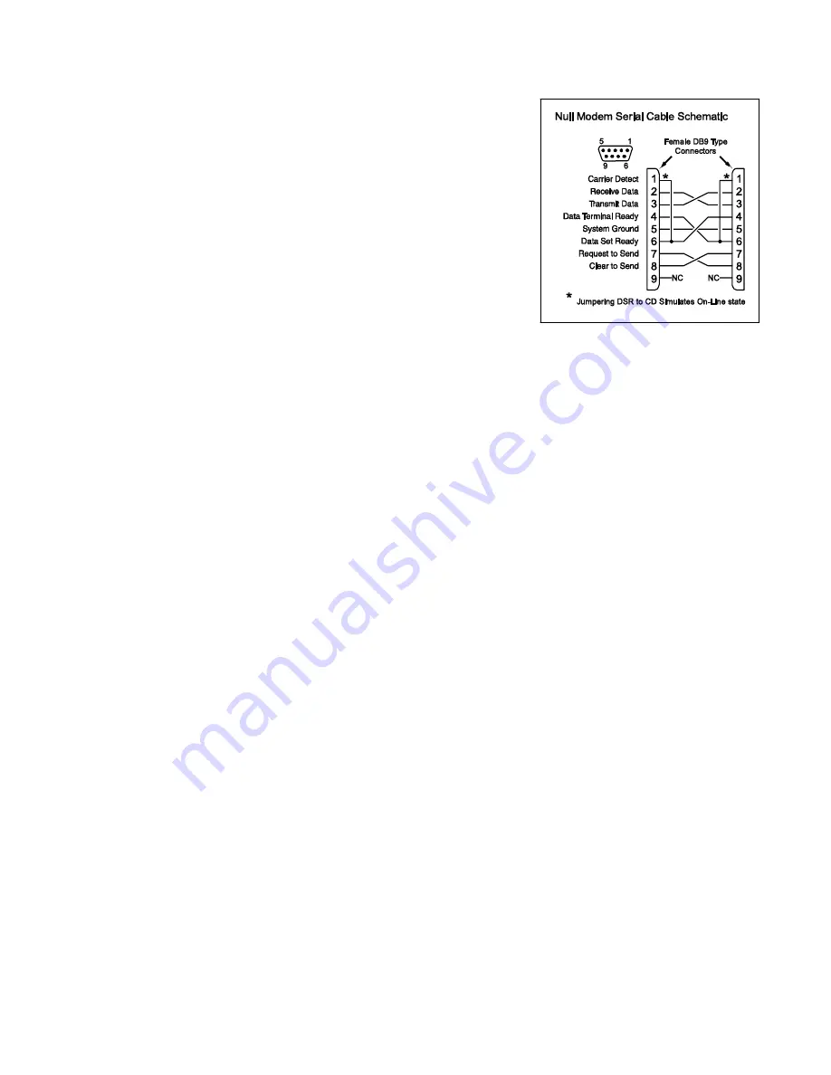
Figure 2:  Null Modem Serial Cable 

Appendix B: Pan, Tilt & Zoom


RS232 Protocol: 

• Connect Dome to Pins 2(Rx) and Pin 3(Tx) of the DB9 Connector that plugs into the     

male DB9 connector on the V4000 module. 


RS485 Protocol: 

• The RS485 Protocol requires an RS232 to RS485 adaptor. Contact your vendor for 

details. 

• Connect Dome to TxDA Pin 1(-) and TxDB Pin 2(+) of the DB9 Connector that 

plugs into the male DB9 connector on the V4000 module. 


1. 

Dial up the V4000 module from 

Control Center Software 

installed on a PC 

 
2. Select 

Tuning 

icon > 

Unit Power on parameters 

Modems. 

• Select the required protocol from the list box. 
• Select the required Baud rate using the radio buttons (Typically 2400 - 19200). 


3. Click 

on 

Upload

. Disconnect, connect and restart unit. 

 
4. 

Dial up V4000 from 

Control Center Software 

to receive Video from the dome. 

 
5. 

Click on the icon located in the upper left-hand corner of the video screen you 
wish to control. 

 
6. Select 

Unit Peripheral Setup 

from the dialog box that appears. 

• Set the speed of the Dome camera. 
• Set the Sweep Mode, Resolution and Quality settings. These settings 

determine and frame rate and screen quality during dome camera movement. 

• Enter the ID number of the dome camera. The ID Number should be 1-3 

digits. Check with vendor for correct dome ID Number. 


7. Click 

OK 

to save settings. 

Summary of Contents for V4000

Page 1: ... m m mo o o o o o o ot t t t t t t te e e e e e e e V V V V V V V Vi i i i i i i id d d d d d d de e e e e e e eo o o o o o o o S S S S S S S Sy y y y y y y ys s s s s s s st t t t t t t te e e e e e e em m m m m m m m Installation and Setup Guide Installation and Setup Guide Installation and Setup Guide Installation and Setup Guide ...

Page 2: ...2 ...

Page 3: ...are Installation 10 Setting Screen Resolution and Color Palette 10 Initial Control Center Operation 11 Entering and Connecting to a New Site 11 System Checkout 11 Troubleshooting 12 Appendix A Direct Connection to PC Laptop Computer 12 Appendix B Pan Tilt Zoom 13 FCC COMPLIANCE STATEMENT 14 LIMITED WARRANTY 16 This manual contains information on limitations regarding product use and functionality ...

Page 4: ...4 ...

Page 5: ...hen the remaining memory is filled recording of video events ceases After the central station call is completed the V4000 takes control of the phone line and calls a previously stored number for the central station that will process the video signal The completed video clip including the pre alarm video and the post alarm video is transmitted to the central station using the internal modem Note Ce...

Page 6: ...ECP Bus 45mA Operating Temperature Range 32 to 131 F 0 50 C Humidity 25 to 80 Non Condensing Resolution 128h x 100v NTSC or PAL 256h x 100v NTSC or PAL 256h x 200v NTSC or PAL 512h x 200v NTSC or PAL Color Resolution 16 8 million colors with 256 gray scales On board Frame Storage 200 Kbytes ...

Page 7: ...l components are mounted wire the unit as follows referring to Figure 2 1 Connect Handset side Tip and Ring on the Control panel to the V4000 Tip and Ring terminals as shown in Figure 2 Note Ensure that all plugs and jacks meet the dimension tolerance and plating requirements of 47 C F R Part 68 Subpart F For proper operation there must not be any additional equipment connected between the control...

Page 8: ...inals of the V4000 module to the control panel s keypad ECP bus using 22AWG 5mm quad twisted two pair wire 5 Connect an ADEMCO AD12612 12VDC 1A power supply to the Power In terminals on the V4000 Caution Ensure that the correct polarity is observed when connecting to the power source Caution Ensure that the negative power input negative power output circuit common and unit chassis are tied togethe...

Page 9: ...rogrammed to trigger on two different events two logical outputs which point to the same physical relay must be programmed One of those outputs must be programmed to continuous pulse when it turns on so that the V4000 can differentiate between the messages See the example below 4204 Output Command 4204 on ECP Address 12 Function Relay 1 Turn ON for 2 seconds when zone 1 goes into alarm Captures Vi...

Page 10: ...Choose Destination Location window will appear This screen will determine the directory in which Control Center Software is installed Honeywell recommends installation in the default directory After the destination folder has been chosen click Next to continue 9 Repeat Step 8 for the location of the data files 10 After copying all files to your computer the Select Components screen will appear Two...

Page 11: ...he first connection you must enter a Password 10 A New Site message will appear click OK 11 Video from the site will appear on screen 12 Select the Tuning Icon on the toolbar The Remote Setup dialogue box will appear In this box set the following Set Screen Resolution Set Mode Black White or Color 13 Select the General Tab Program Alarm Phone 1 Phone 2 Select NTSC 14 Select the Advanced Tab Set Bu...

Page 12: ...ontrol Center Software User Guide 5 Zone activation Violate a zone associated with each of the CCTV cameras to verify operation Troubleshooting Unit does not answer Verify the power is on according to the installation instructions Replace the unit with a telephone and call the site If the line is functioning the telephone will ring NO VIDEO message appears in video window Check video signal using ...

Page 13: ...2 to RS485 adaptor Contact your vendor for details Connect Dome to TxDA Pin 1 and TxDB Pin 2 of the DB9 Connector that plugs into the male DB9 connector on the V4000 module 1 Dial up the V4000 module from Control Center Software installed on a PC 2 Select Tuning icon Unit Power on parameters Modems Select the required protocol from the list box Select the required Baud rate using the radio buttons...

Page 14: ...J 31X Telephone Connection Requirements A plug and jack used to connect this equipment to the premises wiring and telephone network must comply with the applicable FCC Part 68 rules and requirements adopted by the ACTA A compliant telephone cord and modular plug is provided with this product It is designed to be connected to a compatible modular jack that is also compliant See installation instruc...

Page 15: ...ine service is subject to state tariffs Contact the state public utility commission public service commission or corporation commission for information If your home has specially wired alarm equipment connected to the telephone line ensure the installation of this equipment does not disable your alarm equipment If you have questions about what will disable alarm equipment consult your telephone co...

Page 16: ...TNESS FOR A PARTICULAR PURPOSE OR OTHERWISE WHICH EXTEND BEYOND THE DESCRIPTION ON THE FACE HEREOF IN NO CASE SHALL SELLER BE LIABLE TO ANYONE FOR ANY CONSEQUENTIAL OR INCIDENTAL DAMAGES FOR BREACH OF THIS OR ANY OTHER WARRANTY EXPRESS OR IMPLIED OR UPON ANY OTHER BASIS OF LIABILITY WHATSOEVER EVEN IF THE LOSS OR DAMAGE IS CAUSED BY THE SELLER S OWN NEGLIGENCE OR FAULT Seller does not represent th...

Reviews: