SV9501/SV9502/SV9601/SV9602 SMARTVALVE
TM
SYSTEM CONTROL
3
69-1270—3
Ignition system controls are set at the factory for natural
or LP gas. Do not attempt to use an ignition control made
for LP gas on a natural gas system. Do not attempt to use
an ignition control made for natural gas on an LP gas
system.
Ignition system controls with standard opening regulators
(SV9501M, SV9502M, and SV9601M) or slow opening
regulators (SV9501H and SV9502H) can be converted
between natural gas and LP gas.
Ignition system controls with step opening regulators (P
suffix) cannot be converted between gases.
Selecting the Valve
Make sure when replacing any SmartValve
TM
that you
know what valve is going in and what valve is coming out.
The SV9501 and SV9502 look slightly different from the
SV9500. The SV9500 features an ON/OFF control knob,
as shown in Fig. 1. The SV9501, SV9502, SV9602, and
SV9601 have an ON/OFF switch, as shown in Fig. 2. The
SV9501, SV9502, SV9601, and SV9602 have a
connector located at the top of the valve instead of on the
front.
The SV9501, SV9502, SV9602, and SV9601 have
identical valve body features and use the same
connectors.
NOTE: The SV9601 and the SV9602 do not have flange
mounting capability.
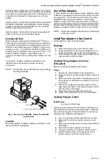
Fig. 1. Front view of SV9500. Notice the ON/OFF
control knob.
Location
Mount the SV9501, SV9502, SV9602, or SV9601 on the
gas manifold in the appliance.
Use of Pipe Adapters
In some field service applications, space limitations make
it difficult or impossible to thread the gas control onto the
gas supply line. This problem can be resolved for many
installations by using a pipe adapter. Install the pipe
adapter on the end of the supply line in place of the gas
control by following the same precautions and instructions
that are used for installing the gas control. After the pipe
adapter is installed, attach the gas control to the adapter.
NOTE: Using a pipe adapter increases the overall length
of the gas control.
Install Pipe Adapter to Gas Control
Install adapter to gas control as follows:
Bushings
1.
Remove seal over gas control inlet or outlet.
2.
Apply moderate amount of good quality pipe com-
pound to bushing, leaving two end threads bare.
3.
Insert bushing into gas control and carefully thread
pipe into the bushing until tight.
Installing Flange Adapters to Control
(If Required)
Mount any necessary adapters as follows:
Flanges
1.
Choose the correct flange for the application.
2.
Remove the seal over the ignition system control or
outlet.
3.
Make sure the O-ring is fitted in the flange groove. If
the O-ring is not attached or is missing, do not use
the flange.
4.
With the O-ring facing the ignition system control,
align the screw holes on the ignition system control
with the holes in the flange.
5.
Insert the screws provided with the flange.
6.
Tighten the screws firmly but do not over tighten
Installing Piping to Control
IMPORTANT
Do not use Teflon® tape.
All piping must comply with local codes or ordinances or
with the National Fuel Gas Code (ANSI Z223.1 NFPA No.
54), whichever applies. Tubing installation must comply
with approved standards and practices.
1.
Use new, properly reamed pipe that has no chips.
2.
Make sure the ends are square, deburred, and
clean.
3.
Make sure all tubing bends are smooth and without
deformation.
4.
Get a tube-to-pipe coupling if necessary.
5.
Run pipe or tubing to the ignition system control.
6.
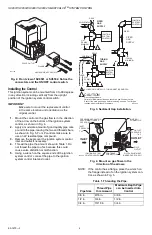
Install a sediment trap in the supply line to the
ignition system control as shown in Fig. 3.
M3342A
VALVE OUTLET
FLANGE
9/64 INCH HEX SCREWS (4)


