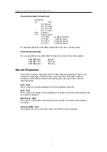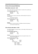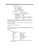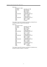
Touchpoint 4 Serial Communication Protocol Issue 1 09/07
PHYSICAL LAYER
Preamble
The physical layer of Touchpoint4 serial communication protocol is an electrical
interface in accordance with EIA/TIA-485 standard (also known as RS485 standard). In
Touchpoint4 serial communication system, a Master Device and one or several Slave
Devices communicate on a balanced twisted pair, on which bi-directional data are
transmitted, at the bit rate as user configured.
Electrical Interfaces
Multipoint Serial Bus Infrastructure
Touchpoint4 Serial Communication system implements a “Two-Wire” electrical interface
in accordance with EIA/TIA-485 standard. On such a 2W-bus, at any time only one
driver has the right for transmitting.
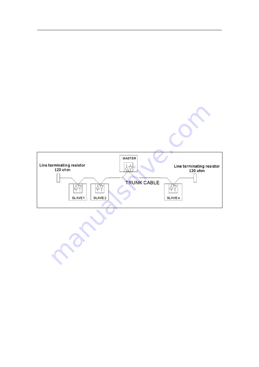
The following figure gives a general overview of the serial bus infrastructure in
Touchpoint4 Serial Communication system.
Figure 6. Communication infrastructure
The Touchpoint4 gas detector controllers are connected directly to the trunk cable.
The master, PC or PLC, is connected directly or via a derivation, according to the
master instruction. The cable should be shielded.
Note: the Touchpoint4 RS-485 interface is not electrically isolated. A common mode
voltage of 7 volt or greater between any two nodes on the network will interfere with
communications. Proper earthing of every Touchpoint4 and the Master is essential.
Multipoint System requirements
Maximum number of devices:
Although a figure of 32 devices is always authorized on any RS485 system without
repeater, the total number is limited to 16 in Touchpoint4 Serial Communication protocol
because of addressing limitations.
12

