Touchpoint 4 Serial Communication Protocol Issue 1 09/07
1
Introduction
Overview
This manual describes the setup and operation of the Touchpoint 4 Serial
Communication protocol.
Your Touchpoint 4 gas detector controller is equipped with a serial remote device
communication port. With this communication port, you can monitor the Touchpoint 4
system’s operation with master from a remote location. It will also allow you to gather
gas concentration data for analysis or reports.
The Touchpoint 4 gas detector controller accepts commands and issues responses to
any valid command it receives. The Touchpoint 4 gas detector controller is always the
“slave” device, and the remote equipment is the “master” device. The master can be a
personal computer (PC), a programmable logic controller (PLC), or other device capable
of RS-485 serial communications. This configuration requires a “master” device.
Therefore, one Touchpoint 4 gas detector controller will not communicate directly with
another Touchpoint 4 gas detector controller. However, one master can be used to
communicate with more than one Touchpoint4 gas detector controllers on a two-wire
RS-485 bus.
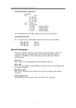
The Touchpoint 4 gas detector controller supports multiple baud rates. These user
selectable rates are 1200, 2400, 4800, 9600, and 19,200. Additional port settings are
8-bit, 1 stop bit, and no parity.
The slave is identified by an address configured into the Touchpoint 4 gas detector
controller (selectable 1-16). Each Touchpoint4 gas detector controller on an RS-485
network must have a unique address.
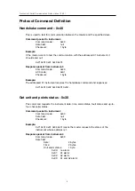
The master is always at address 0. Each Touchpoint 4 gas detector controller will
respond to a signal directed to it from the master. To prevent a collision of messages, the
master must avoid transmitting any information after a packet until the slave responds.
Touchpoint 4 will respond in 500ms.


