
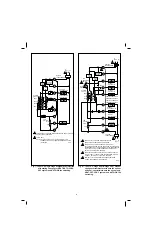

SYSTEM
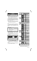
PRESS LOOK FOR THIS RESPONSE
SWITCH
THIS
KEY
KEY
POSITION
KEY
DOWN
RELEASED
OFF
03
Blank
07
Blank
15
Blank
COOL or
15
1st stage cooling,
AUTO (with
fan and SYSTEM
fan in AUTO)
LED on.
15
2nd stage cooling
also on.
15
2nd stage cooling off.
15
1st stage cooling, fan
and SYSTEM LED off.
NOTE: If single-stage cooling system, press key twice
instead of 4 times; once to turn cooling, fan and SYS-
TEM LED on, second time to turn off.
OFF
06
Blank
02
Blank
05
Blank
04
Blank
01
Blank
00
Blank
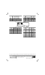
(CHECK
12
See note A
EACH
POSITION)
OFF
08
Blank
13
Microprocessor mask
no. and revision no.
09
Blank
14
Blank
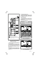
HEAT or
14
1st stage heating and
AUTO 1
SYSTEM LED on.
14
2nd stage heating
also on.
14
2nd stage heating off.
14
1st stage heating and
SYSTEM LED off.
NOTE: If single-stage heating system, press key twice
instead of 4 times; once to turn heating and SYSTEM
LED on, second time to turn off.
OFF
10
Blank
11
Normal operating
display.
1
For electric heat fan operation—The fan will operate
with the heating system when fan switch is in AUTO.
A
HEAT displayed when system switch is in HEAT,
COOL when in COOL, HEAT and COOL when in
AUTO, neither when in OFF. Also, a four-digit code is
displayed, with each digit explained below.
7
69-0330—3
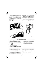
Fig. 13—All segments on display.
2. Set system switch to OFF. Press AHEAD and BACK
and PRESENT SETTING keys at the same time to enter
self-test.
3. Press each key as listed below, and look for response
listed as key is held down and released.
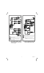
COOLING
CAUTION
Do not operate cooling if outdoor temperature is
below 50
°
F [10
°
C]. Refer to manufacturer’s recom-
mendations.
NOTE: When cooling setting is changed, thermostat will
wait up to 5 minutes before turning on the cooling
equipment. This delay protects the compressor.
Move the system switch to COOL and the fan switch to
AUTO. Press COOLER key until the setting is about 10
°
F
[6
°
C] below room temperature. The cooling equipment and
fan should start. Press WARMER key until the setting is
about 10
°
F [6
°
C] above room temperature. The cooling
equipment and fan should stop.
NOTE: On an AUTO changeover thermostat, the heating
temperature must be set at least 3
°
F [2
°
C] below the
cooling temperature, or display will flash.
FAN
Move the system switch to OFF, and the fan switch to
ON. The fan should run continuously. When the fan switch
is in the AUTO position, fan operates directly with the
cooling system, and also with heating system on some
models.
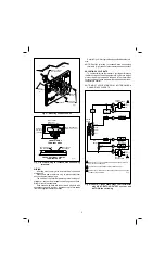
INSTALLER SELF-TEST (optional)
IMPORTANT
•
AC power must be present on thermostat to con-
duct self-test. Relays will not toggle, codes will not
be present and thermostat will not manually exit
self-test without ac power.
•
Five-minute time delay on cooling does not func-
tion during self-test.
Perform the following test as a check of all thermostat
functions. If thermostat does not respond as indicated,
thermostat must be replaced.
1. Press AHEAD and BACK keys at the same time.
While holding keys down, all segments of the display should
be on (Fig. 13).
M525A
AM
SUN
MORNING
REPL
BAT
SET
PT
ROOM
PM
OUTDOOR
TUE WED THU FRI SAT TEMPORARY
MON
MIDDAY EVENING NIGHT COOL ON HEAT ON
SKIP
NEXT
PERIOD
PRESENT
SETTING
PRESENT
SETTING
PRESENT
SETTING
PRESENT
SETTING
PRESENT
SETTING
SET
PRESENT
DAY/TIME
DAY
AHEAD
BACK
SET
PRESENT
DAY/TIME
SET
PRESENT
DAY/TIME
SET
PRESENT
DAY/TIME
SET
PRESENT
DAY/TIME
CHANGE
TO LAST
PERIOD
COOLER
WARMER
COPY
FROM
COPY
TO
PERIOD
CANCEL
PERIOD
SET
HEAT/COOL
HOLD
TEMP
RUN
PROGRAM


