

4
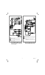
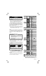
Fig. 8—T8621D 2-stage heat/2-stage cool manual
changeover thermostat with auto fan on heat
and cool; convertible to auto fan on cool only.
HEAT-OFF-COOL system and AUTO-ON fan
switching.
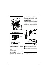
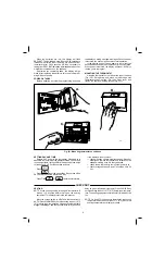
Fig. 7—T8621C,D single-stage heat pump thermostats
with heating changeover. HEAT-AUTO-COOL-
OFF system and AUTO-ON fan switching.
M1576
SYSTEM
TRANSFORMER
R
C
W1
W2
Y2
Y1
G
RC
FAN RELAY
HIGH
LIMIT
HIGH
LIMIT
L1
(HOT)
L2
HEAT
AUTO
COOL
SYSTEM
SWITCH
AUTO
ON
FAN
SWITCH
POWER SUPPLY. PROVIDE DISCONNECT MEANS AND OVERLOAD
PROTECTION AS REQUIRED.
T8621D ONLY.
NOTE:
1
POWER
SUPPLY
OFF
COMPRESSOR
CONTACTOR
HEATING
CHANGEOVER
H1
H2
C1
C2
2
1
2
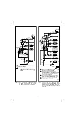
SET CYCLE RATE TO HOT WATER SETTING (3 cph).
THERMOSTAT DOES NOT PROVIDE MINIMUM OFF TIME
IN HEATING.
L1
(HOT)
L2
1
3
4
1
2
3
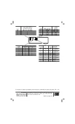
POWER SUPPLY. PROVIDE DISCONNECT MEANS
AND OVERLOAD PROTECTION AS REQUIRED.
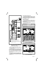
FOR GAS OR OIL APPLICATIONS OR ELECTRIC HEAT
APPLICATIONS WHERE THE FAN OPERATION IS CONTROLLED
INDEPENDENTLY OF THE THERMOSTAT (AUTO FAN OPERATES
WITH Y1 ONLY). TWO TRANSFORMERS MAY BE USED. SET
SWITCH TO NONELECTRIC POSITION.
SYSTEM
SWITCH
FAN
SWITCH
AUTO
ON
OFF
HEAT
COOL
STAGE 1
HEAT RELAY
STAGE 2
HEAT RELAY
STAGE 2
COOLING RELAY
STAGE 1
COOLING RELAY
M13444
HEATING DAMPER OR
CHANGEOVER RELAY
COOLING DAMPER OR
CHANGEOVER RELAY
FAN RELAY
COOLING
TRANSFORMER
HEATING
TRANSFORMER
R
C
W1
W2
B
O
Y2
Y1
G
RC
POWER
SUPPLY
FAN
OPERATION
SWITCH
ELECTRIC
NON-
ELECTRIC
HIGH
LIMIT
HIGH
LIMIT
HEAT 1
HEAT 2
COOL 1
COOL 2
L1
(HOT) L2
1
4
3
2
FOR ELECTRIC HEAT APPLICATIONS (AUTO FAN OPERATES
WITH W1 AND Y1), USE ONLY ONE TRANSFORMER; JUMPER
R AND RC. SET SWITCH TO ELECTRIC POSITION.
NOMINAL 24 VAC POWER MUST BE PRESENT BETWEEN
R AND C FOR THERMOSTAT OPERATION.


