Honeywell T8002, Installation Instructions Manual
The Honeywell T8002 Installation Instructions Manual is a comprehensive guide that enables hassle-free installation of the innovative T8002 thermostat. This user-friendly manual can be effortlessly downloaded for free from our manualshive.com, providing detailed instructions and ensuring a smooth setup process, allowing you to maximize the capabilities of your Honeywell T8002 thermostat.
Share
Download


Reviews:
No comments
Related manuals for T8002

C60
Brand: Fantini Cosmi Pages: 8
517
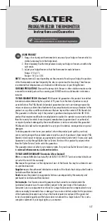
Brand: Salter Pages: 12

Tempo
Brand: Warmup Pages: 8

CT100
Brand: Z-Wave Pages: 18

5343
Brand: Samson Pages: 60

1F87-0261
Brand: White Rodgers Pages: 12

TM 3050-RF
Brand: Technoline Pages: 2

HI 93530
Brand: Hanna Instruments Pages: 14

PCE-889B
Brand: PCE Instruments Pages: 8

00111382
Brand: Xavax Pages: 56

148917
Brand: Kampmann Pages: 2

HH11B
Brand: Omega Engineering Pages: 2

living connect
Brand: Danfoss Pages: 5

03031
Brand: SATA Pages: 59

8920W
Brand: Aprilaire Pages: 11

32062
Brand: York Survey Supply Pages: 2

TYPE 4830
Brand: OBH Nordica Pages: 84

Comark C12 HACCP
Brand: Fluke Pages: 6


