


T775R SERIES 2000 ELECTRONIC STAND-ALONE CONTROLLER
13
62-0249—13
1.
A single reset curve is programmed for the
first output and is used by all outputs setup
with RESET=YES.
2.
For subsequent outputs (MOD and Relay), a
setpoint
offset
is used if that output is also being
Reset. Refer to “1.2.9.1 SETPOINT OFFSET
(subsequent outputs only)” on page 16.
3.
When setback is used, the minimum and maxi-
mum boiler temperature setpoints that were
entered will also be offset by the setback offset.
This may not be desired if it is necessary to
maintain the minimum temperature (to avoid
condensing) or maximum temperature entered
in the reset schedule. In this case, we recom-
mend adjusting the minimum and/or maximum
temperature by the offset so that during set-
back the desired limits are maintained.
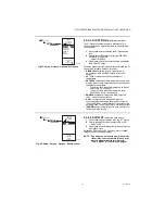
When Reset is programmed, the home screen
conveniently displays the calculated Heat/Cool setpoint(s)
for the Mod and Relay outputs based on the reset curve
(Refer to Fig. 21 on page 10).
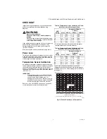
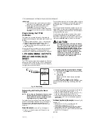
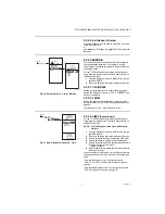
Fig. 25. Reset Curve for First Output with
Setback Offset.
The remainder of this section, beginning with “1.2.
Entering Program Mode”, describes the individual
parameters for configuring outputs with Reset.
For your reference, the following Reset programming
procedure uses the values in Fig. 25.
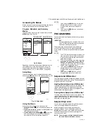
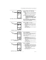
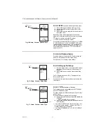
Fig. 26. Program Menu.
1.2. Entering Program Mode
Press the
MENU
button, then select PROGRAM and
press the
button to view the Program menu.
NOTE: Modulating outputs are not available on
controller models T775R2001 and
T775R2035.
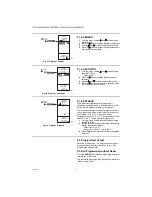
Fig. 27. Setpoint Values for Reset and Setback.
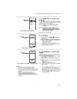
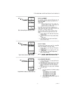
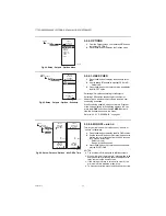
1.2.1. Program Menus for Outputs with
Reset
Press the
MENU
button, select PROGRAM, then select
RELAY 1 (or MOD 1) to view the parameters.
The Reset settings (Figures 28 through 31 on page 14)
are programmed for the first output and these settings
apply to all outputs that are configured for Reset. See
Fig. 25 on page 13 for the reset curve values used in the
following section.
NOTE: The Setback parameter displays only if
scheduling is enabled (refer to Fig. 65 on
page 26) or the DI Option is set to Setback
(refer to Fig. 67 on page 27).
SENSOR B
SP MAX A1
(BOILER MAX)
SP MIN A2
(BOILER MIN)
200
140
10
SETBACK
OFFSET
-10°F
190
20
30
40
50
60
70
°F
80
150
160
170
210
220
180
°F
RESET B1
(OUTSD MIN)
RESET B2
(OUTSD MAX)
S
E
N
S
O
R
A
M24305
OR
MENU
PROGRAM
MENU
PROGRAM
RELAY 1
RELAY 2
RELAY 3
RELAY 4
EXIT
MENU
PROGRAM
MOD 1
MOD 2
RELAY 1
RELAY 2
RELAY 3
RELAY 4
EXIT
M24302
SP MAX A1
RESET B1
SP MIN A2
RESET B2
DIFFRNTL
HEAT/COOL
SETBACK
EXIT
OR
PROGRAM
RELAY 1
MENU
PROGRAM
RELAY 1
BOILR MAX
OUTSD MIN
BOILR MIN
OUTSD MAX
DIFFRNTL
HEAT/COOL
SETBACK
EXIT
MENU
PROGRAM
RELAY 1
RELAY RESET:
YES-OTHER AND
DI OPTION = SETBACK
RELAY RESET:
YES-BOILER AND
DI OPTION = SETBACK
M24306