Honeywell SHC Series Installation Instructions Manual Download Page 5

OEM SHC CONTROLLER – INSTALLATION INSTRUCTIONS 


MU1B-0441GE51 R0710B 

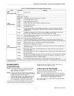
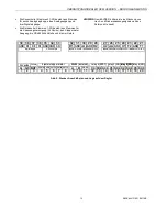
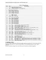
Table 2. LED blinking patterns and corresponding meanings 

LED 

behavior 

meaning 

LED 1 
(green power LED) 

ON 

Power is ON. 

LED 2 
(red alarm LED) 

always ON 

-- 

always OFF 

No alarm 

single blink 

Power failure (the SHC will then run on battery) 

2 blinks 

Low superheat alarm is active 

3 blinks 

High superheat alarm is active 

4 blinks 

Sensor failure due to sensor break or sensor short-circuit 

5 blinks 

LOP protection is active 

6 blinks 

Configuration error 

7 blinks 

Communication failure. Communication with appliance controller is missing. Periodic 
messages are not being received. Bus cable broken or appliance controller has been 
switched OFF. 

8 blinks 

Hardware self-test alarm. One of the following voltages is outside the permitted range: 
motor voltage, relay supply voltage, sensor supply voltage, AO voltage 

LED 3 
(yellow status LED) 

always ON 

SHC is disabled or (due to any error or alarm condition) control is absent (which 
automatically disables the SHC) 

always OFF 

SHC is running without EEV movement 

single blink 

The EEV is opening, closing, or synchronizing. A single blink (until the OFF position is 
achieved; EEV in safety position; REV to close) also indicates that the SHC is powering up. 

2 blinks 

REV valve is moving (i.e., the REV delay time is currently elapsing) 

3 blinks 

Start ramp (incl. holding time) is active 

4 blinks 

“Pump down” is active or the compressor is waiting to switch ON, but the compressor min. 
OFF time is active. 

5 blinks 

MOP protection is active. This LED behavior has a higher priority than “start-up ramp is 
active” (see above) 

6 blinks 

HITCond protection is active. This LED behavior has a higher priority than “start-up ramp is 
active” (see above) 

7 blinks 

Waiting for ALL Enabled conditions. If there is more than just one “SHC Enabled” condition, 
the SHC will wait until 

all

 “SHC Enabled” conditions are TRUE. The conditions can come 

from hardware (DI), network, or Cold store logic. 

8 blinks 

EEV is in the manual override mode; no superheat control from PI control active. 

*Each blink has a duration of 300 msec, with intervals of 300 msec between multiple blinks. The blinking pattern is then repeated 
every few seconds. 


POWER SUPPLY 

General Information 

NOTE:

  Local wiring guidelines (e.g. VDE 0100) may take 

precedence over recommendations provided in 
these installation instructions. 

NOTE:

  To comply with CE requirements, devices having a 

voltage of 50...1000 Vac or 75...1500 Vdc but lacking 
a supply cord, plug, or other means for 
disconnecting from the power supply must have the 
means of disconnection incorporated in the fixed 
wiring. This means of disconnection must have a 
contact separation of at least 3 mm at all poles. 

All wiring must comply with applicable electrical codes and 
ordinances. Refer to job or manufacturers’ drawings for 

details. Use a min. of 18 AWG (1.0 mm

2

) and a max. of 

14 AWG (2.5 mm

2

) for all power wiring. 


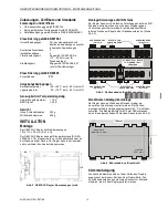
Connecting to the Power Supply 

The power supply (24 Vac [±20%], 50/60 Hz or 24 Vdc 
[±10%]) is connected to terminals 1 and 2. 

NOTE:

  Do not reverse the polarity of the power connection 

cables and avoid ground loops (i.e. avoid connecting 
one field device to several controllers as this may 
result in short circuits damaging your device. 

The maximum power consumption will not be higher than 50 
VA at 24 Vac ±20%. 


Summary of Contents for SHC Series

Page 1: ...ghboring relays may switch the same phase only Sensors and secondary output of transformer may not be grounded simultaneously Grounding of secondary output of transformer is not recommended Alarm relay without power must be recognized as alarm if used A 24 V emergency battery module not included can be connected to the SHC to enable safe closing in the event of a power failure 1 Ah is recommended ...

Page 2: ...20 g With screw terminals 290 g INSTALLATION Mounting The OEM SHC Controller has the dimensions 181 x 110 x 40 mm W x L x H The OEM SHC Controller is suitable for mounting on both a standard rail DIN EN 50022 35 x 7 5 and for installation in wiring cabinets in fuse boxes and on walls ceilings The controller can operate in both horizontal and vertical position 181 40 110 Fig 2 OEM SHC Controller di...

Page 3: ...ists of terminals for power supply 24 Vac dc the output for the bipolar stepper motor the RS485 interface and the four relays NOTE According to VDE guidelines it is not allowed to mix low voltage and high voltage signals on the relays 32 9 A OUT1A OUT1B OUT2A OUT2B EARTH 8 7 6 5 4 3 2 1 G G0 BAT 24 Vbat RS485 isolated relay 4 SPDT relay 1 NO relay 2 NO relay 2 NO relay 3 NO bipolar stepper motor 2...

Page 4: ...ometric 0 10 V 25 GND AIN3 4 ground for universal inputs 1 2 26 V5 15 AIN3 4 sensor voltage supply for universal inputs 1 2 27 U2 AIN3 universal input 2 NTC10K NTC20K Pt1000 0 5 4 5 V ratiometric 0 10 V 28 R2 AIN6 current voltage input 2 0 5 4 5 V 0 10 V 4 20 mA 29 GND AIN6 ground for current voltage input 2 30 V5 15 AIN5 6 sensor voltage supply for current voltage inputs 1 2 31 GND AIN5 ground fo...

Page 5: ...a higher priority than start up ramp is active see above 6 blinks HITCond protection is active This LED behavior has a higher priority than start up ramp is active see above 7 blinks Waiting for ALL Enabled conditions If there is more than just one SHC Enabled condition the SHC will wait until all SHC Enabled conditions are TRUE The conditions can come from hardware DI network or Cold store logic ...

Page 6: ...w to complete the termination Fix the cable using cable binders if required HARDWARE FEATURES Stepper Motor Output The controller is able to drive bipolar stepper motors with 12 V or with 24 V supply voltage The stepper motor is connected to terminals 4 to 8 see terminal assignment with shielded motor cable Stepper Motor Parameters Motor voltage 12 V or 24 V current chopper control Step frequency ...

Page 7: ...t use the relay It always remains OFF REL_COMP_PROTECT_DIRECT REL_COMP_PROTECT_REVERSE The compressor relay is used to protect the compressor In the event of a critical compressor situation it is switched ON direct or OFF reverse to stop the compressor If there is no critical situation the relay is always OFF direct or ON reverse In device manual or remote mode the compressor relay is switched to ...

Page 8: ...f AIN5 and AIN6 configured for current input is max 2 5 Input Resistance The input resistance of AIN5 and AIN6 configured for voltage input is min 20 kOhm The input resistance of AIN5 and AIN6 configured for current input is max 250 Ohm Temperature Impact The temperature impact on AIN5 and AIN6 configured for voltage input is max 1 with respect to a reference temperature 25 C The temperature impac...

Page 9: ...tor fluid supply temperature in REVERSE mode 3 tSole1 Evaporator air inlet temperature 6 to2 Suction line temperature 7 to1 Evaporating fluid supply temperature 9 tV2 Condenser fluid supply temperature 14 pV2 Condenser fluid supply pressure 17 po2 Suction line pressure 20 dp Evaporator air differential pressure NOTES Sensors and secondary output of transformer cannot be grounded simultaneously Sen...

Page 10: ...Fig 8 Wiring for brine water heat pump Air Water Heat Pump A complete control system for the control of an air water heat pump could consist of SHC controller SHC X9999 Power supply ETR2 EEV EV2 EEV cable EEVCABS Pressure sensor PSR MS UB MP150 PSR cable PSR CAB300 MP150 Temperature sensor TS NFR for superheat temperature Temperature sensor TS NFR for air inlet temperature Differential pressure se...

Page 11: ...lten Sensoren und Transformator Ausgang dürfen nicht gleichzeitig geerdet werden Die Erdung des Trafo Ausgangs ist nicht erforderlich Falls das Alarm Relais benutzt wird muß der spannungslose Zustand als Alarm interpretiert werden Um bei Spannungsausfall ein sicheres Schließen des Expansions ventiles zu gewährleisten kann ein 24 V Notfall Batteriemodul nicht im Lieferumfang mit einer Kapazität von...

Page 12: ...chaltschrank oder an der Wand oder der Decke Der Regler kann in horizontaler und in vertikaler Position betrieben werden 181 40 110 Abb 2 OEM SHC Regler Abmessungen mm Montage Demontage auf DIN Schiene Der Regler kann durch einfaches Aufschnappen auf eine DIN Schiene montiert werden und mit einem Stopper gegen Verrutschen gesichert werden Er wird demontiert durch leichtes Ziehen am Bügel an der Ge...

Page 13: ... von Hoch und Niederspannungssignalen an den Relais nicht erlaubt 32 9 A OUT1A OUT1B OUT2A OUT2B EARTH 8 7 6 5 4 3 2 1 G G0 BAT 24 Vbat RS485 isolated relay 4 SPDT relay 1 NO relay 2 NO relay 2 NO relay 3 NO bipolar stepper motor 24 Vac dc B GNDX 10 11 12 C4 NO4 NC4 C1 NO1 C2 NO2 C3 NO3 13 14 15 16 17 18 19 20 39 38 37 36 35 34 33 inputs 4 20 mA ratiometric 0 10 V digital inputs 0 10 V output inpu...

Page 14: ...AIN3 4 Sensor Spannungsversorgung für Universaleingänge 1 2 27 U2 AIN3 Universaleingang 2 NTC10K NTC20K Pt1000 0 5 4 5 V ratiometrisch 0 10 V 28 R2 AIN6 Strom Spannungseingang 2 0 5 4 5 V 0 10 V 4 20 mA 29 GND AIN6 Masse für Strom Spannungseingang 2 30 V5 15 AIN5 6 Sensor Spannungsversorgung für Strom Spannungseingänge 1 2 31 GND AIN5 Masse für Strom Spannungseingang 1 32 R1 AIN5 Strom Spannungsei...

Page 15: ...rrichtung in der festen Verdrahtung haben Diese Trennvorrichtung muß einen Kontakt abstand von mindestens 3 mm an allen Kontakten haben Sämtliche Verdrahtung muß anwendbaren Gesetzen und Vorschriften entsprechen Siehe Hersteller Zeichnungen Für den Anschluß der Spannungsversorgung mindestens 18 AWG 1 0 mm und maximal 14 AWG 2 5 mm verwenden Anschluss an die Spannungsversorgung Die Spannungsversorg...

Page 16: ...itte Öffnungsschrittzahl 1 1 000 Schritte Neben den elektronischen Expansionsventilen Typ EEV von Honeywell Modelle EV2 EV3 EV4 hat der Regler Vor einstellungen für die in Tabelle 3 gelisteten Schrittmotor ventile mit den zugehörigen Parametern Diese Ventile können einfach durch Anwahl des Ventiltyps konfiguriert werden Andere Ventile die den oben beschriebenen Schrittmotor Parametern entsprechen ...

Page 17: ...mpressore Relais wird genutzt um den Verdichter abhängig von Startfunktion Kühlstellenregelung Kreislaufumkehr Abtauung ein und auszuschalten Diese Funktionsweise ist nur möglich wenn die Kühlstellenregelung aktiviert ist REVERSE REL_REV_REQ_NOT_USED Der Regler nutzt das Relais nicht Es bleibt immer AUS REL_REV_REQ_DIRECT Der Regler schaltet das Relais EIN solange der Kältekreislauf im Umkehrbetri...

Page 18: ...IN5 und AIN6 konfiguriert als Spannungseingang ist max 1 bezogen auf eine Referenztemperatur von 25 C Der Temperatureinfluß auf AIN5 und AIN6 konfiguriert als Stromeingang ist max 1 bezogen auf eine Referenz temperatur von 25 C Analogausgang Der SHC Regler kann über einen Spannungsausgang Klemmen 33 35 ein Spannungs Ausgangssignal 0 10 V bereitstellen Max Stromaufnahme Die höchste Strombelastung d...

Page 19: ...rittstemperatur Verdampfer 6 to2 Sauggastemperatur 7 to1 Verdampfereintrittstemperatur 9 tV2 Heißgastemperatur 14 pV2 Kondensationsdruck 17 po2 Saugdruck 20 dp Luft Differenzdruck am Verdampfer HINWEISE Sensoren und Transformator Sekundärseite Ausgang dürfen nicht gleichzeitig geerdet werden Sensoren mit Stromausgang 4 20 mA und mit ratio metrischem Spannungsausgang 0 5 V 4 5 V können nicht gleich...

Page 20: ...hlußbelegung für Sole Wasser WP Luft Wasser Wärmepumpe Ein komplettes Regelsystem zur Regelung einer Luft Wasser Wärmepumpe besteht aus SHC Regler SHC X9999 Spannungsversorgung Transformator ETR2 EEV EV2 EEV Kabel EEVCABS Drucksensor PSR MS UB MP150 PSR Kabel PSR CAB300 MP150 Temperatursensor TS NFR für Überhitzungstemperatur Temperatursensor TS NFR für Lufteintrittstemperatur Differenzdrucksensor...

Reviews: