


OEM SHC CONTROLLER – INSTALLATION INSTRUCTIONS
MU1B-0441GE51 R0710B
3
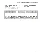
154 mm
1
0
0
m
m
oval hole
(4x7 mm)
round hole
(diameter: 4 mm)
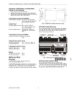
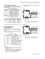
Fig. 4. Drilling template (view from above)
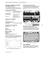
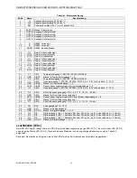
Terminal Assignment
The terminal blocks are arranged on two sides of the con-
troller: the sensor side and the relay side. The terminals on
the controller consist of multiple sockets for screw terminal
plugs which come together with the controller.
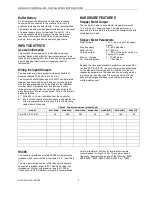
The sensor side (terminals 21-39) consists of terminals
for six analog inputs, one analog output, and three digital
inputs.
The relay side (terminals 1-20) consists of terminals for
power supply (24 Vac/dc), the output for the bipolar
stepper motor, the RS485 interface, and the four relays.
NOTE:
According to VDE guidelines, it is not allowed to mix
low-voltage and high-voltage signals on the relays.
32
9
A
OUT1A
OUT1B
OUT2A
OUT2B
EARTH
8
7
6
5
4
3
2
1
G
G0 BAT
24 Vbat
RS485 (isolated)
relay 4 (SPDT) relay 1 (NO)relay 2 (NO)
relay 2 (NO)relay 3 (NO)
bipolar stepper motor
24 Vac/dc
B
GNDX
10
11
12
C4
NO4 NC4
C1
NO1
C2
NO2
C3
NO3
13 14 15 16 17 18 19 20
39 38 37 36 35 34 33
inputs: 4...20 mA / ratiometric / 0...10 V
digital inputs
0...10 V output
inputs: Pt1000, NTC10k, NTC20k / ratiometric / 0...10 V
R1
GND
AO
GND
GND
GND
D3
D2
D1
GND
GND
GND
V5/15
V5/15
R2
U2
U1 T2
T1
31 30 29 28
27 26 25 24 23 22
21
Fig. 5. Terminal layout and location on controller