


S9361A207X INTEGRATED BOILER CONTROLLERS
69-2751—05
8
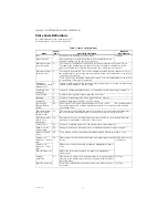
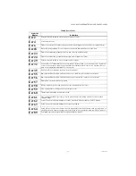
State Code Definitions
For induced draft - state codes from 1–17;
For atmospheric - state codes from 1–21
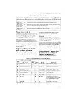
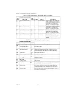
Table 5. State Code Definitions.
State
State
code
Specific Description
General
Description
Idle
1
The boiler is in standby-no call for heat
Standby
Run circulator
Heat request present but boiler temp sufficiently high to run
circulator pump only (no ignition sequence)
Wait for pressure
switch to open
2
The inducer is off and the control waits for the pressure switch to open. This is
checked at the beginning of a heat cycle before turning on the inducer. If the
pressure switch doesn't open in 60 seconds, the control goes to state 11.
Wait for pressure
switch to close
3
The inducer is turned on. The control is waiting for the pressure switch to close at
the beginning of a cycle. If the pressure switch doesn't close within 60 seconds, the
control goes to state 12
3secs safety relay test delay time when status 4 or 6 is interrupted pressure switch
to open. Then control goes to state 12
Prepurge
(includes PV short
diagnostics)
4
System is purging before ignition trial-safety relay diagnostics followed safety relay
switch-on during last 2 secs this state
Spark, Ignition
activation
6
System is sparking permanently 13 seconds whilst main valve relay is turned on
Prove Flame
7
System is proving flame signal, typically 2 seconds
Running
8
System is in running mode, flame signal must be present.
Postpurge
9
System is purging at the end of a call for heat
Inter-purge
(Retry/ Recycle
Delay)
10
If the control loses flame signal during state 7 or 8 , it will
recycle through the 30 seconds purge time and last 2secs.part
of prepurge time
Re-Start delay due
to flame failure
Wait for pressure
switch to open -
failed closed
11
The inducer is still off, and the pressure switch has not opened at the beginning of
the heat cycle. An alarm message is sent but the control is not in lockout.
Wait for pressure
SW to close -
failed open
12
The inducer is still on, waiting time for pressure switch to close expired. An alarm
message is sent but the control is not in lockout.
Soft Lockout
13
System is shutdown and will re-start following an enforced delay
Hard Lockout -
non-volatile
14
System is locked out. A manual reset is required to be able to light off again
Wait for Limit to
Close
15
There may be a call for heat from the thermostat, but the limit switch is open.
flame out of
sequence - before
trial
16
Flame signal sensed before trial for ignition. Appropriate alarm
is sent
Flame present out
of sequence
flame out of
sequence - after
trial
Flame out of sequence during postpurge. Appropriate alarm is
sent
Wait for flame loss
Flame signal still present when not expected. Appropriate
alarm is sent
Leakage
Detection
17
HW self check, check of connected periphery, it is performed at
start up, in the beginning of the heat cycle and in the "Wait For
Recovery" state
Self Test
Wait For Recovery
There is an external error and the control is waiting to recover,
no lockout
Self Test