Honeywell S9361A207 Series Installation Instructions Manual Download Page 12

S9361A207X INTEGRATED BOILER CONTROLLERS

69-2751—05

12

Mounting Sensor and 
Thermowell

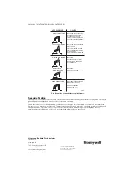
The remote upper temperature sensor is installed in 
an immersion well (Fig. 6) that extends into the supply 
water side of the boiler.

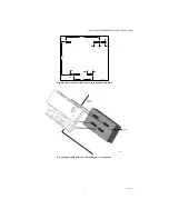
Immersion Well Fitting

The immersion well must snugly fit the sensing bulb 
for good thermal response. Install as follows:

1.

Use tapping provided by tank manufacturer, if 
possible, or select an area where typical water 
temperature is best measured.

2.

If tank is filled, drain to below point where bulb 
will be installed.

3.

Screw well into tank.

4.

Insert bulb into well, pushing wires until bulb 
bottoms in well.

5.

Attach mounting clamp end of well spud.

6.

With mounting clamp attached to well spud 
(make sure jaws of clamp hook over ridge at end 
of spud, as shown at points A in Fig. 6), adjust 
sensing leadwire to fit through mounting clamp 
groove, as shown at point B in Fig. 6.

7.

Tighten draw nut until mounting clamp is firmly 
attached to well spud and wires are held securely 
in place.

CAUTION

Do not secure draw nut so tightly that 
mounting clamp collapses tubing. 

Fig. 6. Immersion well fitting for sensor.

Wiring

Disconnect power supply before installation to 
prevent electrical shock or equipment damage. All 
wiring must comply with local codes and ordinances 
regarding wire size, type of insulation, enclosure, etc.
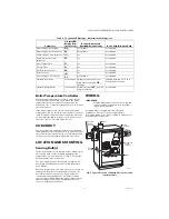
OPERATION AND 
CHECKOUT

Operation

The S9361A207x continuously monitors the 
temperature of the boiler water and enables or 
disables the burner based on this temperature data. In 
general, when a “Call for Heat” occurs, the ignition 
portion of the control module proceeds through the 
steps necessary to start the burner and heats the 
water in the boiler until the setpoint temperature is 
achieved. At this point the burner is de-activated, the 
ignition module completes the heating cycle, returns 

to idle and waits for the temperature to drop again. 
The circulator is turned on throughout the “Call for 
Heat.”

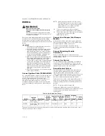
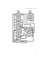
See Fig. 7 for a graphical representation of a simple 
control cycle. Note that the setpoint differential may 
vary based on OS number.

High Limit Controller

All models include a 3-wire temperature sensor 
interface, “Boiler temperature,” which is utilized for 
High Limit functionality in addition to the 
thermostatic control of the water heater burner. If the 
temperature sensor ever indicates a temperature 
above the maximum limit then the control enters over 
temperature mode. In over temperature mode no 
heating will occur.

Fig. 7. Basic control algorithm example.

Thermal Purge Operation

Thermal Purge Feature

When there is a Heat Request active, the circulator will 
be started and boiler firing will be delayed until the 
inferred heat load cannot be met by the residual heat 
of the water in the system.

Boiler Firing Pre-purge

After a Heat Request is detected, the system pump is 
started and the Pump pre-purge Timer starts. Boiler is 
off during Pump pre-purge time.

Boiler Firing Pre-purge Expiration

After Pump pre-purge timer reaches its maximum 
given by Pump Pre-purge Time parameter and the 
Heat Request is still active, the boiler is started.

Boiler Firing Pre-purge Termination

If boiler firing is postponed and water temperature 
drops below 140 °F (field adjustable), the boiler shall 
be started after a 15 second delay regardless of the 
Pump pre-purge timer value. When a Heat Request is 
detected and the boiler water temperature is already 
less than 140 °F (field adjustable), the boiler start 
sequence is initiated after 15 seconds regardless of 
the Pump pre-purge timer value. Once the boiler is 
started, the Pump pre-purge timer is considered to be 
expired until the next heating cycle.

SENSOR WIRES

M23086A

HEAT-CONDUCTIVE COMPOUND

(OPTIONAL)

BOILER

IMMERSION 

WELL

SENSOR

M27000

SETPOINT

GAS VALVE OFF

GAS VALVE ON

70°F (21°C)

200°F (93.3°C)

15°F (8°C)

DIFFERENTIAL

Summary of Contents for S9361A207 Series

Page 1: ...culator and Domestic Hot Water Circulator output Enabled with EnviraCOM communication capability to support remote monitoring and diagnostics Limit rated Temperature Sensing Probe One Sensor Model SPECIFICATIONS IMPORTANT The specifications given in this publication do not include normal manufacturing tolerances Therefore an individual unit may not match the listed specifications exactly Also this...

Page 2: ...c 0 5 to 0 6 PF Ambient Ratings Humidity 0 to 95 percent relative humidity noncondensing Operating Ambient Temperature 4 F to 150 F Shipping Ambient Temperature 40 F to 175 F Flame Monitoring May vary by model Flame Establishing Period FEP Maximum 2 sec onds Flame Failure Response Time FFRT Maximum 2 5 seconds 1 µA Flame Lost Threshold 0 23 µA Accessories Ordered Separately W8735Y1000 Wireless Out...

Page 3: ...sary shield the controls to protect them from splashing water A NEMA 4 enclosure is recommended High Humidity or Dripping Water Over time dripping water or high ambient humidity can create unwanted electrical paths on the module circuit board causing the module to fail Never install an appliance where water can drip on the controls In addition high ambient humidity can cause the control to corrode...

Page 4: ...ecially so in commercial agricultural and industrial applications because 1 In such applications particularly commercial the equipment can operate 100 000 to 200 000 cycles per year Such heavy cycling can wear out the gas control in one to two years A normal boiler application for which the controls were intended typically operate fewer than 10 000 cycles per year 2 Exposure to water dirt chemical...

Page 5: ...EGRATED BOILER CONTROLLERS 5 69 2751 05 Fig 2 Recommended slot hole pattern in appliance in mm Fig 3 Align module with slots in manufacturer s control box 100 M24198 16 16 55 4 99 5 4 WATER HEATER CONTROL BOX M24229 ...

Page 6: ...ic standoff insulators as required 1 Connect one end of the cable to the male quick connect SPARK terminal on the module 2 Connect the other end of the cable to the igniter or igniter sensor stud on the pilot burner igniter sensor Connect Vent Damper Vent Damper Models A vent damper can be used with modules provided with a vent damper plug connector The Molex plug provided simplifies wiring connec...

Page 7: ...etail Fig 4 Spark to Pilot Ignition Wiring S936X M533506 C R D DHW CIRCULATOR ENVIRACOM SYSTEM CIRCULATOR L1 GND L2 DAMPER OPTIONAL INDUCER OPTIONAL 24VAC TRANSFORMER SENSOR DHW T STAT LIMIT SWITCH PRESSURE SWITCH PV PV MV GAS CONTROL SPARK IGNITER FLAME SENSE MV ...

Page 8: ...n running mode flame signal must be present Postpurge 9 System is purging at the end of a call for heat Inter purge Retry Recycle Delay 10 If the control loses flame signal during state 7 or 8 it will recycle through the 30 seconds purge time and last 2secs part of prepurge time Re Start delay due to flame failure Wait for pressure switch to open failed closed 11 The inducer is still off and the p...

Page 9: ...a three digit number and the corresponding degree designator See Display Readout Integrated Boiler Control One Rod Combined Ignitor and Sensor Model Displays See Table 6 8 for the IBC display screens Wait for vent damper to open 18 Damper actuator is energized and the system waits for damper to close Wait for vent damper to close 19 Damper actuator is de energize and the system waits for damper to...

Page 10: ...reen 3rd Screen StA State number Status bt Sensed temperature F or C Boiler Temperature SP Operating Setpoint F or C Operating Setpoint the lowest of the IQ Outdoor air reset EnviraCOM message Desired Boiler Setpoint high limit setpoint and setpoint from the remote user interface device HL_ High Limit F or C Adjust High Limit Setting HdF High Limit Differential F or C Adjust High Limit Differentia...

Page 11: ...mpound Honeywell part no 107408 to fill the space between the bulb and the well to improve heat transfer characteristics optional Make sure the sensor is held firmly in the well WIRING IMPORTANT For maximum trouble free operation run the sensor leadwires separately from any other current carrying wires All wiring must comply with local codes and ordinances Disconnect power supply before beginning ...

Page 12: ...e heating cycle returns to idle and waits for the temperature to drop again The circulator is turned on throughout the Call for Heat See Fig 7 for a graphical representation of a simple control cycle Note that the setpoint differential may vary based on OS number High Limit Controller All models include a 3 wire temperature sensor interface Boiler temperature which is utilized for High Limit funct...

Page 13: ...H OR CALL FOR HEAT LOST SWITCH OPEN SWITCH CLOSE SWITCH OPEN FLAME DEB ON FLAME DEB OFF TIME OUT TIME OUT OR MANUAL RESET LIMIT SWITCH OPEN TIME OUT FLAME SENSED FLAME PROVED TIME OUT WATER TEMPERATURE HIGH OR THERMOSTAT CALL FOR HEAT LOST RETRY DELAY TIME OUT A TIME OUT RECYCLE DELAY DAMPER PRESSURE SWITCH OPEN CHECK FLAME POST TRIAL FLAME DEB ON FLAME DEB OFF FLAME LOST A TIME OUT A TIME OUT TIM...

Page 14: ...out of posi tion restore to correct position STEP 3 Check spark ignition circuit Disconnect the ignition cable at the SPARK terminal on the module WARNING The ignition circuit generates over 10 000 volts and electrical shock can result Energize the module and listen for the audible sparking noise When operating normally there should be a buzzing noise that turns on and off twice per second for a d...

Page 15: ...s duringA D conversion Err 35 Duplicate Zone alarm was received from zone panel Err 55 Atmospheric Damper End Switch failed to close end switch contacts stuck open Err 56 Atmospheric Damper End Switch failed to open end switch contacts stuck closed Err 57 Flame Rod shorted to burner ground Err 58 AC line frequency error signal is too noisy or frequency is incorrect Err 59 Line voltage error voltag...

Page 16: ...risk Tamper evident tape has been placed on the bulk pack box to indicate if the package was opened Do not accept or use product received with damaged or missing tape Reverse engineering or modification of device is not permitted and may pose a safety risk LAZY YELLOW FLAME WAVING BLUE FLAME NOISY LIFTING BLOWING FLAME HARD SHARP FLAME SMALL BLUE FLAME CHECK FOR LACK OF GAS FROM CLOGGED ORIFICE FI...

Reviews: