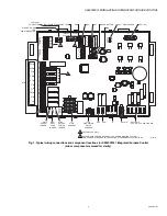
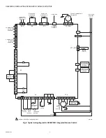


S9240F2051 MODULATING INTEGRATED FURNACE CONTROL
7
69-2807—01
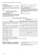
SETTINGS AND ADJUSTMENTS
Jumpers
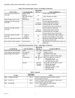
Three jumpers are located on the S9240F board. The jumpers
are all ON (uncut) from the factory. To change any jumper, first
disconnect the power, then cut the desired jumper.
Fig. 3. Jumper locations.
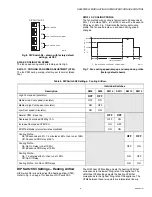
DIP Switches
There are three DIP switch blocks on the S9240F (see Fig. 4):
• S1 – see “DIP Switch S1 Settings”
• S2 – see “DIP Switch S2 Settings – Cooling Airflow” on
• S3 – see “DIP Switch S3 Settings – Heating Airflow” on
Fig. 4. DIP Switch locations (S1, S2, and S3).
DIP Switch S1 Settings
Four parameters may be set with this 7-position DIP switch.
Refer to Fig. 4 for location of DIP switch S1.
The default factory settings (all OFF) are shown in Fig. 5 and
indicated in Bold in Table 5 on page 8.
To change any setting, first disconnect the power, then set
SW1
through
SW7
according to Table 5 on page 8.
Fig. 5. DIP Switch S1 - shown with factory default
settings; all OFF.
SW1: STAGE SELECTION
The stage selection is factory-set (OFF) to a 2-stage
thermostat with the 2nd and 3rd stage On Delays disabled.
The ON position configures the IFC for a single stage
thermostat with the 2nd and 3rd stage On Delays enabled.
NOTE: Selection of the single stage position (ON) allows
three stage operation with a single stage
thermostat.
Table 4. Jumper Conditions - Defaults in Bold.
Description
Jumper
W915
W951
W914
Single stage compressor
Uncut
2-stage compressor
Cut
Disable compressor heating
Uncut
Enable compressor heating
Cut
Disable dehumidifying
operation
Uncut
Enable dehumidifying
operation
Cut
M28642A
(W915) 2 STAGE COMPR
(W914)
DEHUM
(W951) HEAT PUMP
M28643
S2
S3
S1
DIP SWITCH S1
M33119
HEAT FAN OFF DELAY
2ND STAGE ON DELAY
SINGLE OR 2-STAGE THERMOSTAT
SELECTION
ON
1
2
4
3
5
7
6
CONVENTIONAL 2-STAGE OR
MODULATING SEQUENCE
NOT USED