


S9240F2051 MODULATING INTEGRATED FURNACE CONTROL
27
69-2807—01
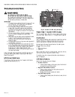
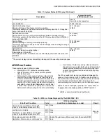
LED Error Codes
There are four types of LED error codes:
— Warning Only: IFC continues normal operation.
— Wait for Recovery: IFC resumes normal operation
after fault recovers.
— Soft Lockout: A state caused by failure internal to the
control or by a system fault such as loss of flame or
pressure switch failure. Heating related functionality is
inhibited during Soft Lockout. Assuming the fault that
sent the IFC to Soft Lockout has cleared, Soft Lockout
exits after the Auto Restart Delay when a call for heat
is active. The operator can cycle power to remove the
Soft Lockout without waiting for the Auto restart Delay.
— Hard Lockout: A state caused by a failure internal to
the control or by a system fault such as a flame rollout.
Heating related functionality is inhibited during Hard
Lockout. Hard Lockout can be exited only by cycling
power to the IFC.
The IFC is capable of clearing, recalling and displaying the
previous 10 error codes. Up to 100 alarms can be stored in
non-volatile memory. The IFC provides the ability to clear the
10-error buffer as described in Table 9 on page 25. In
communicating mode, error history can be read and cleared.
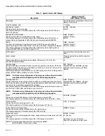
Tables 12 and 13 identify the possible error codes. Table 13
on page 29 lists the codes specific to LSOM
a
operation.
Fault Memory is clear.
0 0 0 0
Return to normal operation
Vent Calibration
C A L
(Pause)
Heat Pump heating stage:
Shows what stage of heat pump currently operating.
The display example in this table shows the LED display when the 1st stage heat
pump is active with 950 CFM:
H 1
(Pause);
A 9 5 0
Dehumidification mode:
Shows that the unit is providing dehumidification instead of straight cooling.
The display example in this table shows the LED display when dehumidification is
active with 1050 CFM:
d
(Pause);
A 1 0 5 0
Cooling Stage:
Shows what stage of cooling is currently operating.
The display example in this table shows the LED display when 2nd stage cooling is
active with 1530 CFM:
C 2
(Pause);
A 1 5 3 0
Defrost Mode:
Shown only while in an active defrost.
(Simultaneous Y, W, and O)
The display example in this table shows the LED display when defrost is active with
870 CFM:
d F
(Pause);
A 8 7 0
a
The current display mode is immediately interrupted if the operating mode changes.
Table 11. System Status LED Display. (Continued)
Description
Display Example
a
(LED display in bold)
a
LSOM = Lennox System Operating Monitor
Table 12. LED Error Codes Displayed By The S9240F2051 IFC.
Error/Fault Condition
Code
IFC Error Handling
(in addition to displaying error code)
Result
Outside air sensor (OAS) out of range
a
(open or no discharge air sensor is OK)
180 None
Warning
Only
Low flame in run mode
240 None
Discharge air sensor (DAS) out of range
a
(open or no discharge air sensor is OK)
310 None
Firing rate reduced to match CFM
311 Reduce firing rate every 60 seconds to match available CFM.
Restricted airflow cooling or continuous fan
312 None