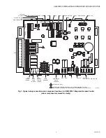
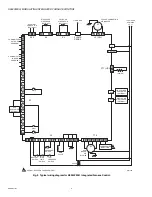


S9240F2051 MODULATING INTEGRATED FURNACE CONTROL
69-2807—01
2
SPECIFICATIONS
Electrical Ratings
Line Voltage Supply:
97-120 Vac, 58-62 Hz; single phase
(132 Vac and 62 Hz maximum)
Input Voltage:
18-24 Vac (30 Vac maximum)
Input Current:
500 mA (control only)
Current Draw:
0.5 A Input Current plus valve load and
optional 24 VAC humidifier load at 24Vac
Igniter Current:
1.0 A maximum resistive at 120 Vac output
Induced Draft Blower:
33-110 Vac; 45-180 Hz; 1.1 A at
110 Vac 3-phase (full load)
Gas Valve:
1.5 A at 30 Vac; Inrush current 3.0 A at 30 Vac;
Inrush duration 16 ms
Line Voltage Humidifier:
1 A resistive load maximum at
120 Vac
Low Voltage Humidifier (option):
1A resistive at 24 Vac
Electronic Air Cleaner:
1 A resistive load maximum at
120 Vac
Gas Control:
Honeywell VK8105R or VR9205R variable firing
rate, 24 Vac valve
Cooling Contactor:
Any 24 Vac contactor rated at 1.0 A or
less
Timings
Prepurge:
15 seconds
HSI Warm-up:
20 seconds
Trial for Ignition:
4 seconds
Ignition Stabilization Period:
30 seconds
Flame Failure Response Time:
2 seconds maximum
Gas Valve Sequence Period:
20 seconds
Postpurge:
20 seconds (15 seconds at current fire rate and 5
seconds at 40% fire rate)
Interpurge:
15 seconds
Auto Restart Delay:
60 minutes (after Soft Lockout)
Ignition Trials:
Five total; four retries if flame is not sensed on
the first trial
Ignition Recycles:
4 total; 3 recycles if flame lost on first trial
Second Stage Recognition Delay:
30 seconds (only on First
Call for High Fire on a Call for Heat)
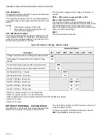
Second Stage ON Delay:
7 or 12 minutes - when used with a
single stage thermostat (see Table 5 on page 8); default is
7 minutes
Third Stage ON Delay:
10 minutes - when used with a single
stage thermostat
Fan Delays:
Heat Fan ON Delay: 30 seconds
Heat Fan OFF Delay: 60, 90, 120, or 180 seconds; default
90 seconds; see Table 5 on page 8
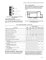
Cool Fan ON Delay: 2 seconds plus selected Cooling Pro-
file; see Table 6 on page 9
Cool Fan OFF Delay: selected Cooling Profile; see Table 6
Circulator Speeds:
Heat: various settings available; see Table 7 on page 10
Cool: low, medium-low, medium-high, and high speeds
available; see Table 6 on page 9
Fan (Thermostat G terminal): continuous fan CFM is 38%
of the circulator speed that is set by switches 8 and 9 on
DIP switch 2; see Table 6 on page 9.
LED
The 7-segment LED communicates:
• System status
• Error codes
• Enables, via a pushbutton, alternate modes (Idle,
Diagnostic, and Field Test) of operation
Operating
Operating Temperature:
-40°F to +175°F (-40°C to +79°C)
Storage Temperature:
-40°F to +185°F (-40°C to +85°C)
Relative Humidity:
0% to 95% non condensing
Approvals
CSA
ANSI Z21.20
INSTALLATION
When Installing This Product…
1.
Read these instructions carefully. Failure to follow them
could damage the product or cause a hazardous
condition.
2.
Check the ratings given in these instructions to make
sure the integrated furnace control is suitable for your
application.
3.
Installer must be a trained, experienced service
technician.
4.
After installation is complete, check out operation as
provided in these instructions.