26
Installation
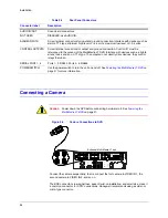
Connecting a Camera
Caution
Power down the DVR before connecting hardware to it. See
Figure 2-2
Camera Connections to DVR
Connect the camera sequentially; that is, connect the first camera to VIDEO IN 1, the
second camera to VIDEO IN 2, and so on.
The BNC connector’s low signal loss, ease of twist-on installation, and small size, make it
a common connector for CCTV connections. Honeywell recommends using a solder- or
crimp-type connector.
AUDIO IN/OUT
Sound card connectors.
NOT USED
DISABLED; use AUDIO IN.
ALARM INPUTS
Screw terminal connectors for input and ground connection. Interface with devices such as
alarms. TTL type: minimum high level of +2.4 volts; maximum low level of +0.4 volts.
CONTROL OUTPUTS
Screw terminal connectors for output and ground connection. Control I/O must be
referenced to the ground of the Multi-Media LT DVR. Interface with devices such as: lights,
sirens, locks, and so on. TTL type. The outputs do not directly drive devices; they control
relays that do so.
SERIAL PORT 1–4
Ports 1–2: RS232. Ports 3–4: RS485.
POWER SWITCH
Use the power switch to turn the unit on and off. See
Powering the Multi-Media LT DVR
for more information.
Table 2-2
Rear Panel Connectors
Connector label
Description
1
2
S ERIAL PO RT 2
S ERIAL PO RT 1
V GA
TE LCO
US B
USB
LAN
IN
OU T
N OT
U SE D
1
2
3
4
5
6
7
8
SPOT
MONITOR
VIDE O
IN PUTS
COMMON
SYS FAIL
SYS GOOD
F
AULT
RELAY
28V, 3A
MAX
1 G
G
G
G
2
3
4
CON TROL
OUT PUTS
SE RIAL
POR T 3
SE RIAL
POR T 4
1 G
G
G
G
2
3
4
5 G
G
G
G
6
7
8
ALA RM
INPUTS
ON/OFF
POW ER
115-230V ~
50/60 Hz
5-3A
8-channel Multi-Media LT unit
Summary of Contents for Rapid Eye LT
Page 1: ...Document 800 07766V1 Rev A 02 11 Installation Guide Rapid Eye LT Digital Video Recorder ...
Page 2: ......
Page 3: ...Installation Guide ...
Page 14: ...14 Contents ...
Page 16: ...16 Figures ...
Page 18: ...18 Tables ...
Page 76: ...76 ...
Page 77: ......

