P7810A-D PRESSURETROL® CONTROLLER
65-0268—1
10
1.
Record the original location of the Limit setpoint knob.
Make sure that the Limit setpoint knob is set (moved to)
a lower value than the Maximum Fixed Stop Limit Value
setpoint. The green LED will be reflective of the call for
heat status and the yellow LED will blink slowly.
IMPORTANT
Do not decrease the Limit Setpoint knob far enough
to cause a lockout.
2.
Very slowly increase the Limit setpoint knob until the
yellow LED begins to blink fast. The current position of
the Limit setpoint now represents the Maximum Fixed
Stop Limit Value setpoint stored in memory.
3.
Return the Limit setpoint knob to the original location
(step
1
).
Setting High Limit Set Point (P7810C,D)
After the Maximum Fixed Stop Limit Value has been stored
into memory, adjust the Limit Setpoint knob to the desired
pressure value at which safety shutdown (lockout) will occur
when the vessel pressure exceeds this setpoint value.
NOTE: The High Limit setpoint value can be less than or
equal to the Maximum Fixed Stop Limit Value but
cannot be set to a value higher than the Maximum
Fixed Stop Limit Value.
Pressure On/Off Control (P7810A,B,C,D)
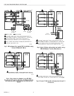
Adjust the setpoint and differential using the potentiometer
knobs on the front of the controller. The differential is a
subtractive value from the setpoint adjustment. The upper
operating point is determined by the control setpoint, while the
lower operating point is determined by the control range
setting (control setpoint minus the differential setting).
Set the potentiometer knobs to the desired point by aligning
the center of the arrow on the potentiometer knob with the
desired mark on the scale plate. See Fig. 13.
Yellow light emitting diode (LED) ON constantly indicates
power applied; green LED On indicates closed contact or call
for heat.
Modulate Control (P7810B,C Only)
The P7810B,C adds 4 to 20 mA modulation output and uses
two additional potentiometers. The pressure sensor output is
fed to an error and gain amplifier to perform the modulation
determined by the control potentiometer settings.
The potentiometer knobs mounted on the P7810B,C face
adjust the current output for a given set of pressures.
The modulation range is an additive value to the modulation
setpoint value.
LED Display (Tables 7 and 8)
The yellow LED is always lit with power applied to the P7810
Pressuretrol® Controller. The microprocessor changes the
brightness of the yellow LED to indicate normal operation,
turns the green LED on and off to indicate call for heat status
and flashes both LEDs to indicate a fault.
NOTE: The term “flashing” means on/off/on/off for the green
LED and bright/dim/bright/dim for the yellow LED.
Press and hold the Reset Switch to access internal
diagnostics. The green (right) LED will flash a series of long
followed by a series of short flashes. Count the long and short
flashes and check the fault code table (Table 8) for
information. For example: four long and three short flashes is
code 43. If you miss the code the first time, keep holding the
Reset Switch down and the code will repeat. Letting go of the
Reset Switch clears the fault information and resets the
P7810.
Table 7. P7810 Blink Codes.
Yellow
Green Control
State
Off
Off
Device off.
No LEDs blinking
Device on, Central Processing Unit (CPU) malfunction.
Slow Blink
Off
Run mode, output off, Limit potentiometer setpoint used.
Slow Blink
On
Run mode, output on, Limit potentiometer setpoint used.
Fast Blink
Off
Run mode, output off, Internal Maximum Fixed Stop Value setting
used.
Fast Blink
On
Run mode, output on, Internal Maximum Fixed Stop Value setting
used.
Alternating Fast Blinks
Lockout, output off, high limit exceeded, Alarm output engaged.
Simultaneous Fast Blinks
Lockout, output off, internal fault, Alarm output engaged.
On, Bright
Fast Blink
Output off, internal Maximum Fixed Stop Value setting not set.

