background image

N200-102-00

6

I56-3947-200  

Notifier Ltd., Charles Avenue, Burgess Hill, West Sussex, RH15 9UF, UK

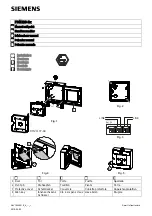
Figure 11:  Front Panel Display

11b:  NFXI-ASD12 1 Channel Detector (2 Sensors)

11a:  NFXI-ASD11 1 Channel Detector (1 Sensor)

FRONT PANEL

The front panel will be different depending on which of the 3 NFXI-

ASD models is being installed, and each is shown below.
The following information is displayed:
•   Detector Status: Normal, Alarm, Fault or Isolate

•   Alarm  Level;  Alarm,  Pre-Alarm  (only  available  with  panels 

using Advanced Protocol)

•   Particulate  Levels;  1-9  (only  available  with  panels  using 

Advanced Protocol)

•   Flow Level

•   Test, Reset and Disable Buttons

11c:  NFXI-ASD22 2 Channel Detector

ALARM

PREALARM

MODULE

LEVEL

SMOKE

FAULT

FAULT

POWER

INPUT

SENSOR

ASPIRA

T

OR

E

L

B

A

SI

D

/
M

E

T

S

Y

S

TEMPER

A

TURE

SOUNDER

FIL

TER

LOW

FLOW

HIGH

FLOW

2

10

3

1

4

5

6

7

8

9

MODULE

LEVEL

SMOKE

FAULT

FAULT

POWER

ALARM

PREALARM

INPUT

SENSOR

ASPIRA

T

OR

TEMPER

A

TURE

SOUNDER

FIL

TER

LOW

FLOW

HIGH

FLOW

E

L

B

A

SI

D

/
M

E

T

S

Y

S

2

10

3

1

4

5

6

7

8

9

MODULE 1

LEVEL 1

SMOKE

FAULT

FAULT

POWER

LEVEL 2

SMOKE

MODULE 2

ALARM

PREALARM

INPUT

SENSOR

ASPIRA

T

OR

E

L

B

A

SI

D

/
M

E

S

Y

TEMPERA

TURE

SOUNDER

FIL

TER

LOW

FLOW

HIGH

FLOW

S

T

2

10

3

1

4

5

6

7

8

9

2

10

3

1

4

5

6

7

8

9

2.   Check the voltage at the connector. Make sure it is within the 

required voltage range.

3.   If the voltage is within the specified range, connect the power 

connector to the unit.

4.   Close and secure the housing door; verify the fan starts up and 

air flows out of the exhaust port. The unit takes 1-3 minutes to 

initialise and stabilise in normal mode.

Configuring Other Options

To  change  any  of  the  default  options,  it  will  be  necessary  to 

connect  the  detector  to  a  PC/laptop  with  the  PipeIQLT  software 

installed;  see 

USB connection

  section  later  in  this  guide  for 

more information on this (and the FAAST LT Advanced Setup and 

Control Guide).

EXTERNAL RESET

The  default  setting  for  the  configurable  external  input  is  Device 

Reset (terminal block T8). A short circuit connection between these 

terminals will cause the FAAST LT unit to perform a reset.

Summary of Contents for Notifier FAAST LT NFXI-ASD Series

Page 1: ...tor Characteristics Maximum rated switching current under short circuit Is max 0 9A 29V Maximum leakage current IL max with the switch open isolated state 15mA Maximum series impedance with the switch closed Zc max 190 m ohm at 15Vdc 1A Power Reset 0 5s Configurable Input Activation Time 2s min Relay Contact Ratings 2 0 A 30 VDC 0 5A 30 VAC Environmental Ratings Temperature 10 C to 55 C Relative H...

Page 2: ... labels fixed in place This allows the installer to choose the language required for the installation from the Front Panel Labelling Pack Figure 2 shows where the labels need to be placed 1 2 3 Figure 6 Fasten the mounting bracket to the wall Mounting the LT NFXI ASD to the Wall Figure 2 Placing the Front Panel Labels 2 10 3 1 4 5 6 7 8 9 2 10 3 1 4 5 6 7 8 9 IN PU T SE NS OR ASPI RATO R E L B A S...

Page 3: ...e unit Each unit has 2 pipe holes per channel so if installing a 1 channel unit holes 3 and 4 do not function Use Table 1 to locate the holes required for the installation Figure 8 Pipe Holes Table 1 Pipe Holes Used for Each FAAST LT Model Note 1 Pipe holes not used should be kept sealed Note 2 Do NOT glue pipes into the pipe holes Table 1a Maximum Number of Pipe Holes Allowed Per Channel for EN54...

Page 4: ...ANNEL 2 FILTER POWER AND ALARM CONNECTIONS CHANNEL 1 FILTER USB PORT SENSOR COVER POSITION FOR TEST MAGNET POSITION FOR TEST MAGNET Exhaust Pipe SAMPLING AREA SAMPLING AREA 5 6 EARTH BAR MOUNT EARTH BAR MOUNT EARTH BAR OPTIONAL Note 1 All wiring should comply with local requirements and regulations Note 2 Loop wiring must observe the recommendations of the panel manufacturer 3 4 ...

Page 5: ...hen smoke is detected by one of the Aspirated Smoke Detector units but not the other To avoid problems ensure that no VIEW sensors on a loop have addresses set adjacent to the address values set in an Aspirating Smoke Detector POWERING UP Using Default Settings 1 Connect a suitable 24VDC supply complying with European Standard EN 54 4 to pins 1 and 2 on terminal block T1 See Table 2 Table 3 Relays...

Page 6: ...E R F IL T E R L O W F L O W H IG H F L O W E L B A S I D M E T S Y S 2 10 3 1 4 5 6 7 8 9 MODULE 1 LEVEL 1 SMOKE FAULT FAULT POWER LEVEL 2 SMOKE MODULE 2 ALARM PREALARM IN P U T S E N S O R AS PI RA TO R E L B A S I D M E S Y TE MP ER AT UR E S O U N D E R F IL T E R L O W F L O W H IG H F L O W S T 2 10 3 1 4 5 6 7 8 9 2 10 3 1 4 5 6 7 8 9 2 Check the voltage at the connector Make sure it is wit...

Page 7: ...w when initialising POWER FAULT ON Yellow Low power alert high power fault Check the power supply voltage CHANNEL FLOW INDICATORS 1 2 ON Green The LED indicates the air flow for a channel Centre normal flow Left flow low 20 at extreme Right flow high 20 at extreme On 2 channel unit Upper row Ch1 Lower row Ch2 LOW FLOW ON Low flow fault Check filter check pipe network for blockages INPUT 1 BLINK Ex...

Page 8: ...e Mode Opening the cabinet door during normal operation will cause the unit to enter Service Mode The FILTER LEDs will blink the unit will switch off power to the fans and stops communicating with the fire panel the smoke sensors continue to communicate with the panel When the cabinet door is closed the unit restarts automatically Filters Periodic cleaning or replacement of the filters will be req...

Page 9: ...ng normal operation 1 2 3 PipeIQ LT QUICK START INSTRUCTIONS Overview of PipeIQLT The PipeIQLT software program is a convenient and powerful Windows based application that can be used to quickly and accuratelydesignpipenetworks generateconfigurationparameters for correct set up and operation and facilitate commissioning and monitoring of the performance of FAAST LT Aspiration devices PipeIQLT prov...

Page 10: ...uter in the normal way for your operating system Launching To launch the PipeIQLT application double click the PipeIQLT icon on the desktop Or click Start bottom left corner of the Windows screen and then select PipeIQLT from the programs list When the application opens it is possible to start a new project or to monitor or modify an existing project Use the File menu to select New or Open Choose ...

Reviews: