background image


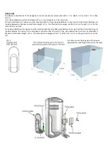
Pict. 4bis: mount the long side of the 
device perpendicular with respect the 
wall of the corridor 

Installation: 

 
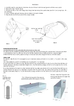
1. Insert the head of a screwdriver in the slot as shown in Picture 2 and then press gently to lift the cover up a bit; 
2. Take off the cover from the tracks; 
3. Hang the sounder on the wall through the 4 fixing holes located on the sounder base (see Pict. 1) and using 4 pcs. of 5‐
mm wall plugs; 
4. In case of system with external pipes, use an adapter to connect all cables; 
5. Close the siren and fix the cover with the screw provided. 


NOTES ABOUT THE DEVICE: 

A cable of 0,33 mm

of


cross sectional


(AVG 22) minimum, must be used. 

The device must be installed by qualified staff only using proper tools and following the manufacturer’s instruction provided 
in this installation sheet. Any other use rather than the one explained in this installation sheet can cause damaged! 
ATTENTION! The device must be powered using a control panel output featuring SELV tension and limited power. 


DSE3‐23 HW 

The device is classified as O. It is designed to cover a maximum volume with side A = 4 m, side B = 7 m, side C = 18 m (See 
Pict. 4). 
It can be installed on a wall at 4 m of altitude or on a ceiling at h = 7 m maximum. 
For wall installation, the device must be installed with the long side perpendicular to the floor and the strobe flashing unit 
looking downwards. Maximum installation height is 4 m, the illumination coverage will be 9 m on the right and 9 m on the 
left and 7 m on front. 
For ceiling installation, the device must be installed with the long side perpendicular to the wall and the strobe flashing unit 
looking  towards  the  space  to  be  illuminated.  Consider  that  the  wall  on  the  side  without  flash  will  be  not  illuminated. 
Maximum installation height is 7 m; the illumination coverage will be 4 m at the front and 9 m at the right and 9 m on the 
left. 


Fixing 
Holes 

Pict. 1 

Pict. 2 

Fix the cover with the 

screw


Insert the screwdriver 

here to open the 

sounder


Summary of Contents for NOTIFIER DSE3-23 Series

Page 1: ...ominal Voltage supply 24Vdc Operating Voltage range 20Vdc 30Vdc Max Current consumption 130mA Vdc 24V DIP1 OFF 110mA DIP1 ON 130mA Max Power consumption 2 6W Max current for sound 20mA 5mA Flash Strobo frequency 0 6Hz or 1 0Hz Main sound frequency average Sound 1 850Hz Main sound pattern Sound 1 Decay from 500Hz to 1200Hz period 1 7s Max level SPL 1 m See Diagram 1 Available Patterns 6 available p...

Page 2: ... ATTENTION The device must be powered using a control panel output featuring SELV tension and limited power DSE3 23 HW The device is classified as O It is designed to cover a maximum volume with side A 4 m side B 7 m side C 18 m See Pict 4 It can be installed on a wall at 4 m of altitude or on a ceiling at h 7 m maximum For wall installation the device must be installed with the long side perpendi...

Page 3: ...allation height is 7 m the illumination coverage will be 5 5 m on the right 5 5 m on the left and 10 m on front For ceiling installation the device must be installed with the long side perpendicular to the wall and the strobe flashing unit looking towards the space to be illuminated Consider that the wall on the side without flash will be not illuminated Maximum installation height is 10 m the ill...

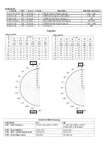
Page 4: ...in dB A 1m min dB A 1m min dB A 1m min dB A 1m 15 75 73 77 75 75 72 45 77 77 75 73 77 72 75 81 80 79 79 82 79 105 81 79 81 80 82 78 135 77 74 75 77 78 75 165 75 76 74 75 76 73 CHART 1 DIPSWITCH setting DIP SWITCH OFF ON DIP 1 Flash frequency 0 6 Hz consumption 110mA 1 0 Hz consumption 130mA SOUND NOT SYNCRONISED DIP 2 Sound patterns From 1 to 3 From 4 to 6 DIP 3 DIP 4 alarm duration timer See Char...

Page 5: ... sound 2 sound 5 SYNC 7 Devices synchronism panels and DSE3 23 sirens Connect to the other SYNC or B terminals S3 8 and 9 trigger for sound 3 sound 6 CHART 2 DIP 3 DIP 4 selection of alarm sound duration DIP3 DIP4 Acoustic alarm duration OFF OFF INFINITE DEFAULT COMPLYING TO EN54 3 ON OFF 3 MINUTES NOT COMPLYING TO EN54 3 OFF ON 8 MINUTES NOT COMPLYING TO EN54 3 ON ON 15 MINUTES NOT COMPLYING TO E...

Page 6: ...ER ITALIA S r l A socio unico 20097 San Donato Milanese Ml Italy Via Grandi 22 Tel 02 518971 Fax 02 5189730 E mail notifier notifier it www notifier it PEC notifier legalmail it Capitale Sociale 2 700 000 00 i v C C I A A 1456164 Trib Milano Reg Soc 348608 Vol 8549 Fasc 8 Codice Fiscale 05108880153 Partita IVA IT 11319700156 informativa privacy art 3 Dlgs 196 03 Uffici Regionali 10143 Torino Corso...

Reviews: