


ML7425A,B SPRING RETURN ELECTRIC LINEAR VALVE ACTUATOR
63-2518-3
6
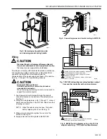
Fig. 9. ML7425 wiring diagram using a 2 to 10 Vdc
output control (e.g., T775) with one transformer.
L1
(HOT)
L2
1
1
WIRING
STRIP
F
+
–
T2
T1
O1
O2
TS
1
1
2
2
3
3
4
5
6
ML7425
T775
(WITH 2-10 VDC OUTPUT)
SINGLE
TRANSFORMER
40 VA 24 VAC
POWER SUPPLY. PROVIDE DISCONNECT MEANS AND
OVERLOAD PROTECTION AS REQUIRED.
M7895
SENSOR
Fig. 10. ML7425 wiring diagram using a 4 to 20 mA
output control (e.g., T775) with two transformers.
L1
(HOT)
L2
1
1
WIRING
STRIP
F
+
–
T2
T1
O1
O2
TS
1
1
2
2
3
3
4
5
6
L1
(HOT)
L2
1
ML7425
T775
(WITH 4-20 MA OUTPUT)
DUAL
TRANSFORMERS
POWER SUPPLY. PROVIDE DISCONNECT MEANS AND
OVERLOAD PROTECTION AS REQUIRED.
M7896
500 OHM
RESISTOR
SENSOR
Fig. 11. ML7425 wiring diagram using a 4 to 20 mA
output control (e.g., T775) with one transformer.
L1
(HOT)
L2
1
1
WIRING
STRIP
F
+
–
T2
T1
O1
O2
TS
1
1
2
2
3
3
4
5
6
ML7425
SENSOR
T775
(WITH 4-20 MA OUTPUT)
SINGLE
TRANSFORMER
40 VA 24 VAC
POWER SUPPLY. PROVIDE DISCONNECT MEANS AND
OVERLOAD PROTECTION AS REQUIRED.
M7897
500 OHM
RESISTOR
Fig. 12. Location of W1, W2 and W3 selector plugs.
M6628
Fig. 13. Replacing cover on ML7425.
Auxiliary Potentiometers
The 43191679 Auxiliary Potentiometers can be used as
feedback potentiometers and to provide remote indication of
the valve position. See the installation instructions packed
with the potentiometers.
Auxiliary Switches
The 43191680 Dual Auxiliary Switch can be used on both the
ML7425A and ML7425B Electric Linear Valve Actuators.
Switching points are adjustable over the full length of the
actuator stroke; for example, the switch can be used to switch
pumps or to provide remote indication of any stroke position.
See the Installation Instructions packed with the auxiliary
switch.
M6631
0 ... 10V
2 ... 10V
W2
10V
0%
10V
W3
W1
100%
50%