Honeywell ML7425A Series Product Data Download Page 5

ML7425A,B SPRING RETURN ELECTRIC LINEAR VALVE ACTUATOR

63-2518-3

5

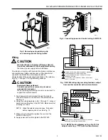
Fig. 5. Removing spring retaining clip

and releasing manual spring handle.

Wiring

CAUTION

Electrical Shock or Equipment Damage Hazard.
Can shock individuals or short equipment circuitry.
Disconnect power supply before installation.

All wiring must comply with local electrical codes, ordinances
and regulations. Voltage and frequency of the transformer
used with the ML7425 must correspond with the
characteristics of the power supply and those of the actuator.
See Fig. 7 through 11 for typical wiring hookups.

CAUTION

Equipment Damage Hazard.
Conduit connection or removal can break an
unsupported connector.
When removing or attaching conduit, use a wrench to
support the metal connector.

1. Feed power and control wires through the conduit

connector located on the bottom of the actuator case.
See Fig. 6.

2. Using the wiring diagrams in Fig. 7 through 11, connect

power and control wires to the ML7425. Make sure that
all wiring is correct.

NOTE:

Make the selector plug changes, if required,
before replacing the cover. See Fig. 12.

3. When wiring is complete, replace the cover on the

ML7425. See Fig. 13.

4. Apply power and control signals to the ML7425.

M6629

Fig. 6. Connecting power and control wiring to ML7425.

M6630

Fig. 7. ML7425 wiring diagram using feedback output

from another controller with one transformer.

POWER SUPPLY. PROVIDE DISCONNECT MEANS AND 
OVERLOAD PROTECTION AS REQUIRED.

F

+

0-10 Vdc OR 2-10 Vdc CONTROL SIGNAL. SEE SIGNAL 
INPUT (+) SECTION.

2-10 Vdc FEEDBACK SIGNAL. SEE OUTPUT SIGNAL 
FEEDBACK SECTION.

ML7425

WIRING
STRIP

F

+

T2

T1

O1

O2

TS

1

3

2

INPUT

(FEEDBACK)

OUTPUT

3

2

1

L1 
(HOT)

L2

C8286B

Fig. 8. ML7425 wiring diagram using a 2 to 10 Vdc

output control (e.g., T775) with two transformers.

L1 
(HOT)

L2

1

1

WIRING
STRIP

F

+

T2

T1

O1

O2

TS

1

1

2

2

3

3

4

5

6

L1 
(HOT)

L2

1

ML7425

T775
(WITH 2-10 VDC OUTPUT)

DUAL
TRANSFORMERS

POWER SUPPLY.  PROVIDE DISCONNECT MEANS AND 
OVERLOAD PROTECTION AS REQUIRED.

M7894

SENSOR

Summary of Contents for ML7425A Series

Page 1: ...everse the direction of action FEATURES Quick and easy installation No separate linkage required ML7425A extends actuator stem on power failure ML7425B retracts actuator stem on power failure Conduit connector is standard No adjustments required True spring return on power failure Accurate valve positioning Low power consumption High close off ratings Force limiting end switches 0 to 10 Vdc or 2 t...

Page 2: ...11H J Screw 150 150 150 145 V5011N1 3 Screw 230 230 163 104 67 37 V5011N2 Screw 100 100 100 100 67 37 V5013B Flange 21 14 V5013C Flange 21 14 V5013F Screw 150 150 150 126 77 49 V5013N Screw 230 230 163 104 67 37 V3350 1 Flange 21 14 V3360 1 Flange 21 b 14 b V3450 1 Flange 21 14 V3460 1 Flange 21 b 14 b Stem Force 135 lbf 600N Actuator Stroke 3 4 in 20 mm Actuator Run Time at 60 Hz 90 seconds Sprin...

Page 3: ...n the instructions and on the product to make sure the product is suitable for your application 3 Installer must be a trained experienced service technician 4 After installation is complete check out product operation as provided in these instructions CAUTION Electrical Shock or Equipment Damage Hazard Can shock individuals or short equipment circuitry Disconnect power supply before installation L...

Page 4: ...ift the handle See Fig 5 7 Remove manual spring handle retaining clip and lift and release the handle See Fig 5 The easiest way to safely perform this operation is to a remove the retaining clip then b wedge a small flat bladed screwdriver under the manual spring handle at the point marked in Fig 5 and pry up the handle Fig 3 Securing ML7425 to valve M6632 Fig 2 Attaching the actuator to the valve...

Page 5: ...wiring diagrams in Fig 7 through 11 connect power and control wires to the ML7425 Make sure that all wiring is correct NOTE Make the selector plug changes if required before replacing the cover See Fig 12 3 When wiring is complete replace the cover on the ML7425 See Fig 13 4 Apply power and control signals to the ML7425 M6629 Fig 6 Connecting power and control wiring to ML7425 M6630 Fig 7 ML7425 w...

Page 6: ...ne transformer L1 HOT L2 1 1 WIRING STRIP F T2 T1 O1 O2 TS 1 1 2 2 3 3 4 5 6 ML7425 SENSOR T775 WITH 4 20 MA OUTPUT SINGLE TRANSFORMER 40 VA 24 VAC POWER SUPPLY PROVIDE DISCONNECT MEANS AND OVERLOAD PROTECTION AS REQUIRED M7897 500 OHM RESISTOR Fig 12 Location of W1 W2 and W3 selector plugs M6628 Fig 13 Replacing cover on ML7425 Auxiliary Potentiometers The 43191679 Auxiliary Potentiometers can be...

Page 7: ...dc FEEDBACK SIGNAL SEE OUTPUT SIGNAL FEEDBACK SECTION ML7425 WIRING STRIP F T2 T1 O1 O2 TS 1 3 4 2 INPUT FEEDBACK OUTPUT 3 2 SP3T OVERRIDE SWITCH 4 1 L1 HOT L2 M7906A CAUTION Equipment Damage Hazard Improper voltage through the 43191680 Dual Auxiliary Switch will damage the switch beyond repair Use the 43191680 Dual Auxiliary Switch with 24 Vac applications only OPERATION General In the ML7425 the...

Page 8: ...g replacement and modernization products from your TRADELINE wholesaler or distributor refer to the TRADELINE Catalog or price sheets for complete ordering number If you have additional questions need further information or would like to comment on our products or services please write or phone 1 Your local Home and Building Control Sales Office check white pages of your phone directory 2 Home and...

Reviews: